
Asynchronous Scheme for Clock Domain Crossing

a clock domain and clock domain technology, applied in the field of asynchronous logic circuits, can solve the problems of different circuits, delay imposed by handshaking circuitry, and metalatability and latency

Active Publication Date: 2011-08-25
INPHI +1
View PDF2 Cites 32 Cited by
  • Summary
  • Abstract
  • Description
  • Claims
  • Application Information

AI Technical Summary

Problems solved by technology

When exchanging transfer data from one clock domain to another several problems emerge, namely metastability and latency.
A typical problem that occurs is when a signal is sampled by a flip-flop triggered by a clock from one domain for sampling data from another clock domain.
That is, in the presence of metastability, a flip-flop might not stabilize to a known state within a certain amount of time, thus leading to circuits that produce different results even given the same logic states and inputs.
The delay imposed by the handshaking circuitry including the aforementioned chain of flip-flops introduces latency.
This latency penalty occurs in each direction and each time transfer data is exchanged between the two clock domains.
In modern systems, a latency of such a magnitude is regarded as a severe timing constraint.
In fact, this increased latency may reduce the actual throughput below the generally desired level of one cycle per cross-domain data transfer.
Still, crossing clock domains with FIFOs may become a bottleneck in the system if the crossing is in a critical loop.
Moreover, prior proposals have included constraining assumptions and / or egregious limitations that motivate the present disclosure.

Method used


Image

  • Asynchronous Scheme for Clock Domain Crossing
  • Asynchronous Scheme for Clock Domain Crossing
  • Asynchronous Scheme for Clock Domain Crossing

Examples


Embodiment Construction

[0039]As fabrication techniques for electronic systems advance, so does the likelihood that a given electronic system will comprise multiple subsystems, each subsystem based on differing clocking schemes. For example, a system might comprise multiple synchronous subsystems (e.g. a heterosynchronous design) in which each of the synchronous subsystems might operate at precise integer multiples of clock speeds or, more likely, each of the synchronous subsystems might drift slightly from the design frequency, resulting from manufacturing and / or environmental variations. Other systems might combine subsystems in some mixture presenting synchronous as well as asynchronous interfaces while each of the subsystems operates within its own clock domain. Still other systems might include one or more subsystems that are designed using pausible clocks.

[0040]In any of the above cases, operation of the system demands reliable and high-performance (e.g. low latency, high bandwidth) communication of ...


PUM


Abstract

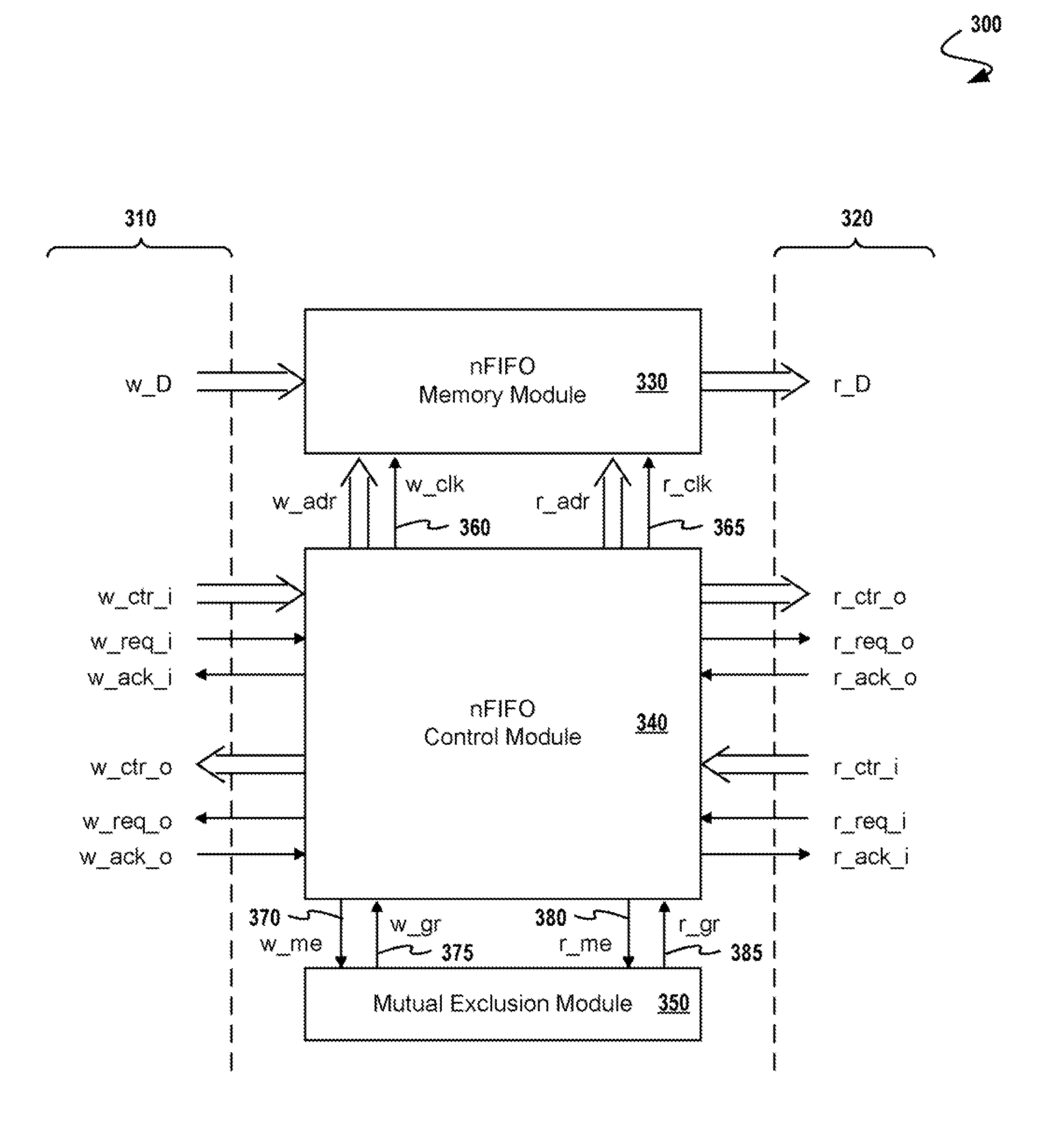
Apparatus and methods for clock domain crossing between a first clock domain and a second clock domain. The apparatus comprises a first control logic element for processing a handshake signal and producing a first arbiter input signal. Concurrently a second control logic element processes a second handshake signal and produces a second arbiter input signal. Exemplary embodiments include exactly one arbiter element inputting the first arbiter input signal, inputting the second arbiter input signal, outputting a first clocking signal to the first sequential element and outputting a second clocking signal to the second sequential element. For managing metastability by controlling the timing of the clocking inputs of the sequential devices, the apparatus includes a first controllable lock delay element selected to satisfy the setup constraint of the second sequential element, and a second controllable lock delay element selected to satisfy the hold constraint of the second sequential element.

Description

FIELD OF THE INVENTION[0001]The present invention relates to asynchronous logic circuits and, more particularly, to low-latency non-blocking communication circuits.BACKGROUND OF THE INVENTION[0002]In the design of systems with multiple clock domains, there is a need to transfer information from one clock domain to another. When exchanging transfer data from one clock domain to another several problems emerge, namely metastability and latency.[0003]Metastability: When the two clocks involved in the transfer are independent, the receiving clock domain sees the incoming signal as an asynchronous signal. In this situation, it is necessary to use techniques to ensure the stability of the incoming signal when it is sampled and propagated through the circuit. A typical problem that occurs is when a signal is sampled by a flip-flop triggered by a clock from one domain for sampling data from another clock domain. That is, in the presence of metastability, a flip-flop might not stabilize to a...

Claims


Application Information

Patent Timeline
Patent Type & Authority Applications(United States)
IPC IPC(8): H03L7/00
CPCG06F7/00H03L7/00
Inventor CORTADELLA, JORDILAVAGNO, LUCIANOMACIAN, CARLOSMARTORELL, FERRAN
Owner INPHI
Learn More