

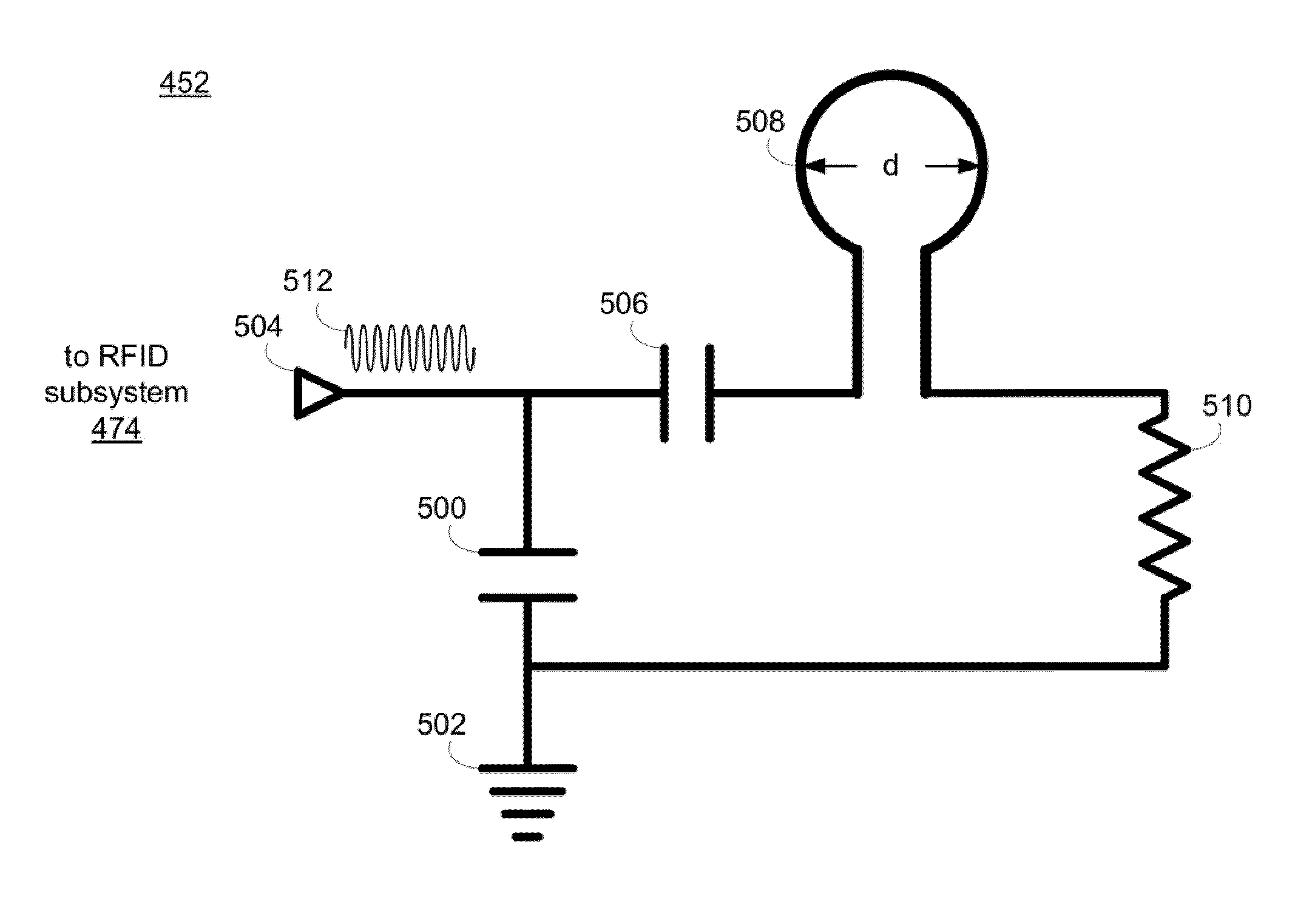
RFID system with an eddy current trap
a technology of eddy current trap and rfid system, which is applied in the field of rfid system, can solve the problems of generating a relatively limited number of products, requiring extensive changes to mechanical/electrical/software systems, and additional components to be added
- Summary
- Abstract
- Description
- Claims
- Application Information
AI Technical Summary
Benefits of technology
Problems solved by technology
Method used
Image

Examples
Embodiment Construction
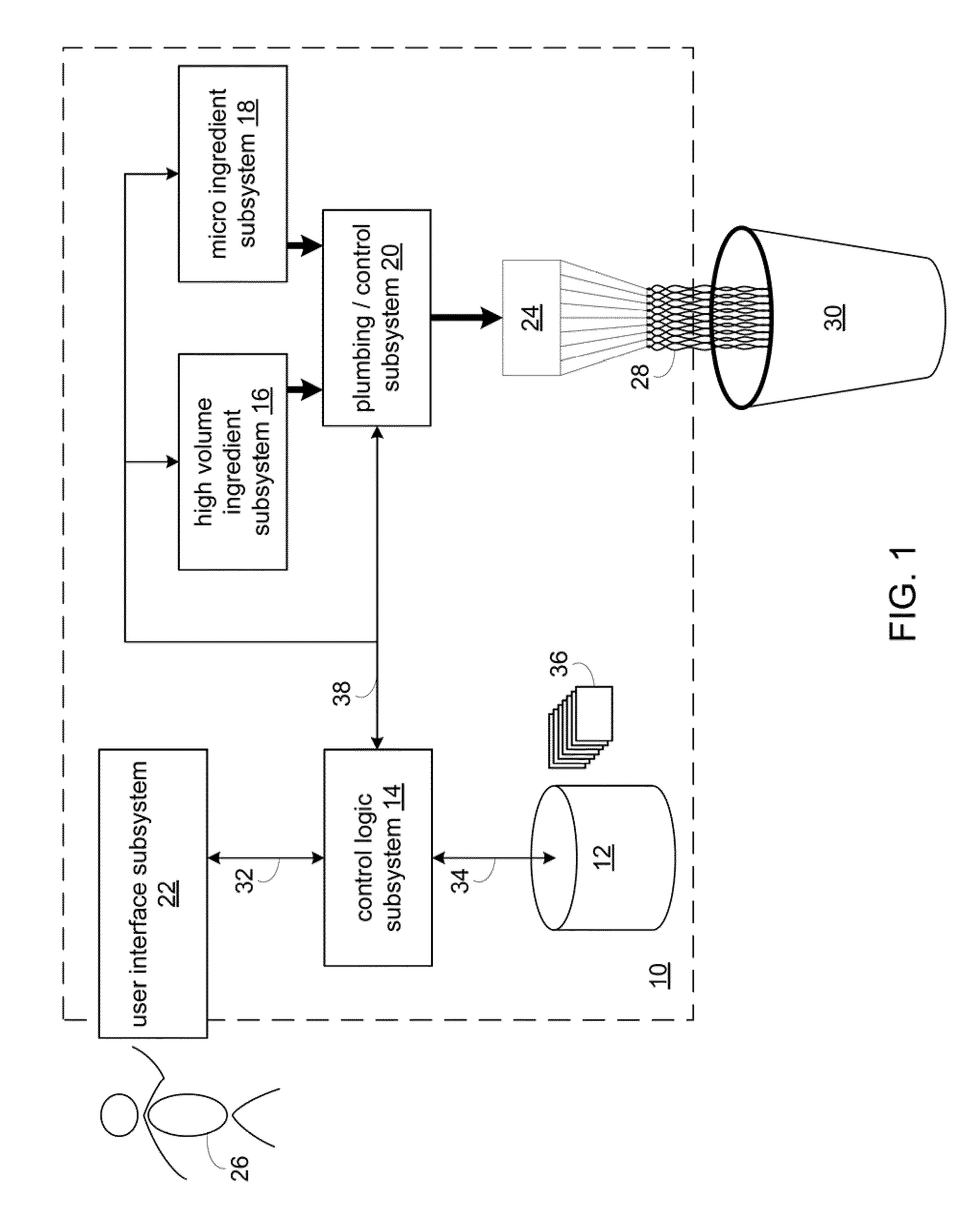
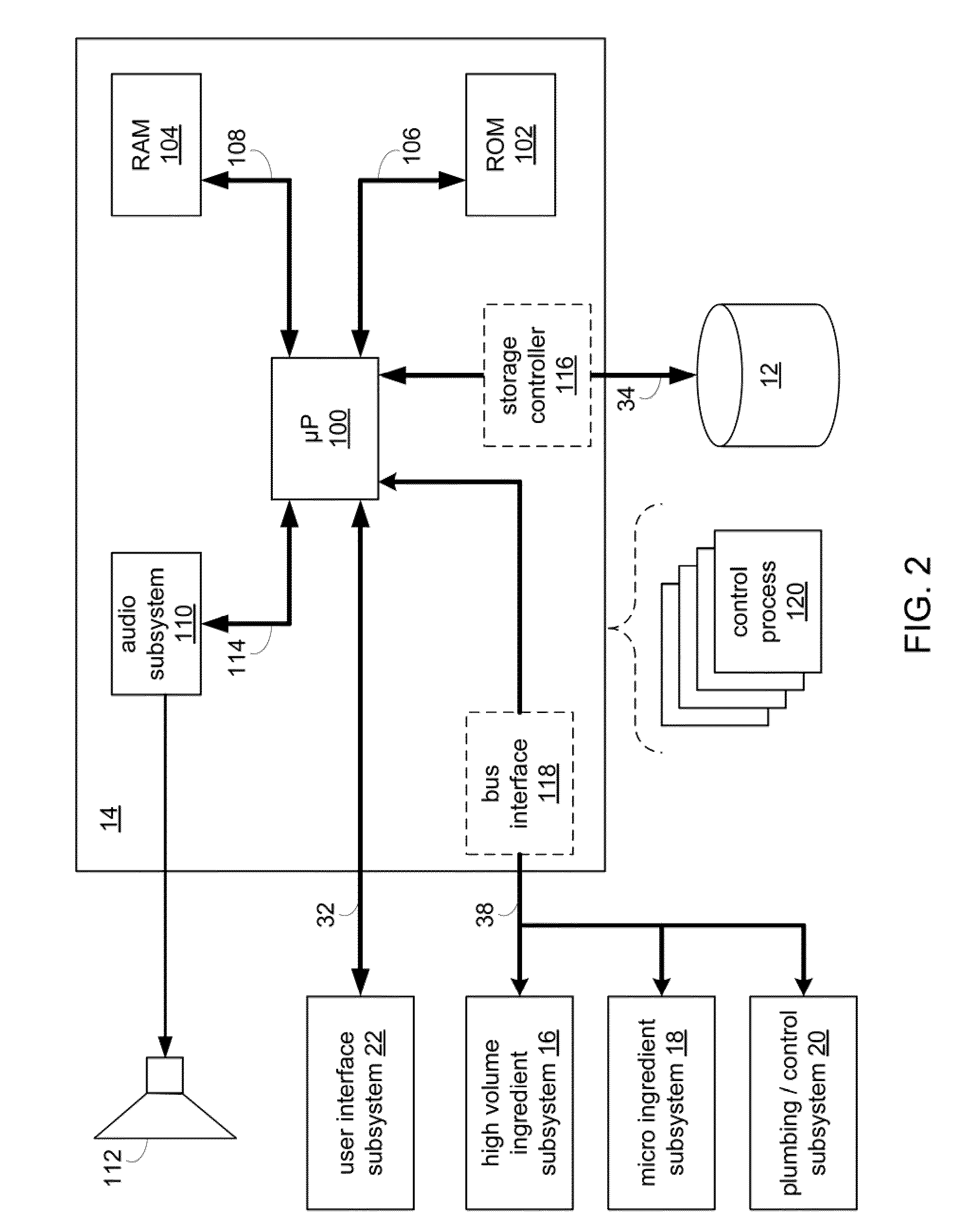
[0056]Described herein is a product dispensing system. The system includes one or more modular components, also termed “subsystems”. Although exemplary systems are described herein, in various embodiments, the product dispensing system may include one or more of the subsystems described, but the product dispensing system is not limited to only one or more of the subsystems described herein. Thus, in some embodiments, additional subsystems may be used in the product dispensing system.
[0057]The following disclosure will discuss the interaction and cooperation of various electrical components, mechanical components, electro-mechanical components, and software processes (i.e., “subsystems”) that allow for the mixing and processing of various ingredients to form a product. Examples of such products may include but are not limited to: dairy-based products (e.g., milkshakes, floats, malts, frappes); coffee-based products (e.g., coffee, cappuccino, espresso); soda-based products (e.g., floa...
PUM
 Abstract
Description
Claims
Application Information