Spot size converter and thermal assist magnetic recording head therewith

a technology of magnetic recording head and spot size converter, which is applied in special recording techniques, instruments, cladded optical fibres, etc., can solve the problems of volume reduction and the reduction of the thermal stability of magnetization, and achieve the effect of shortening the waveguide length, promoting the size reduction of the optical waveguide, and favorable spot size conversion efficiency

Active Publication Date: 2011-08-25
TDK CORPARATION
View PDF14 Cites 84 Cited by
  • Summary
  • Abstract
  • Description
  • Claims
  • Application Information

AI Technical Summary

Benefits of technology

[0023]The spot size converter according to the present invention is capable of shortening the waveguide length in the spot size converter and promoting a size reduction of the optical waveguide itself because two cores are combined and those tapering angles are mutually aligned. Furthermore, spot size conversion efficiency is favorable even in a small size.

Problems solved by technology

However, reducing the size of the magnetic microparticles produces the problem of a reduction in the thermal stability of magnetization that accompanies volume reduction.

Method used


Image

  • Spot size converter and thermal assist magnetic recording head therewith
  • Spot size converter and thermal assist magnetic recording head therewith
  • Spot size converter and thermal assist magnetic recording head therewith

Examples


first experiment

[0186](First Experiment)

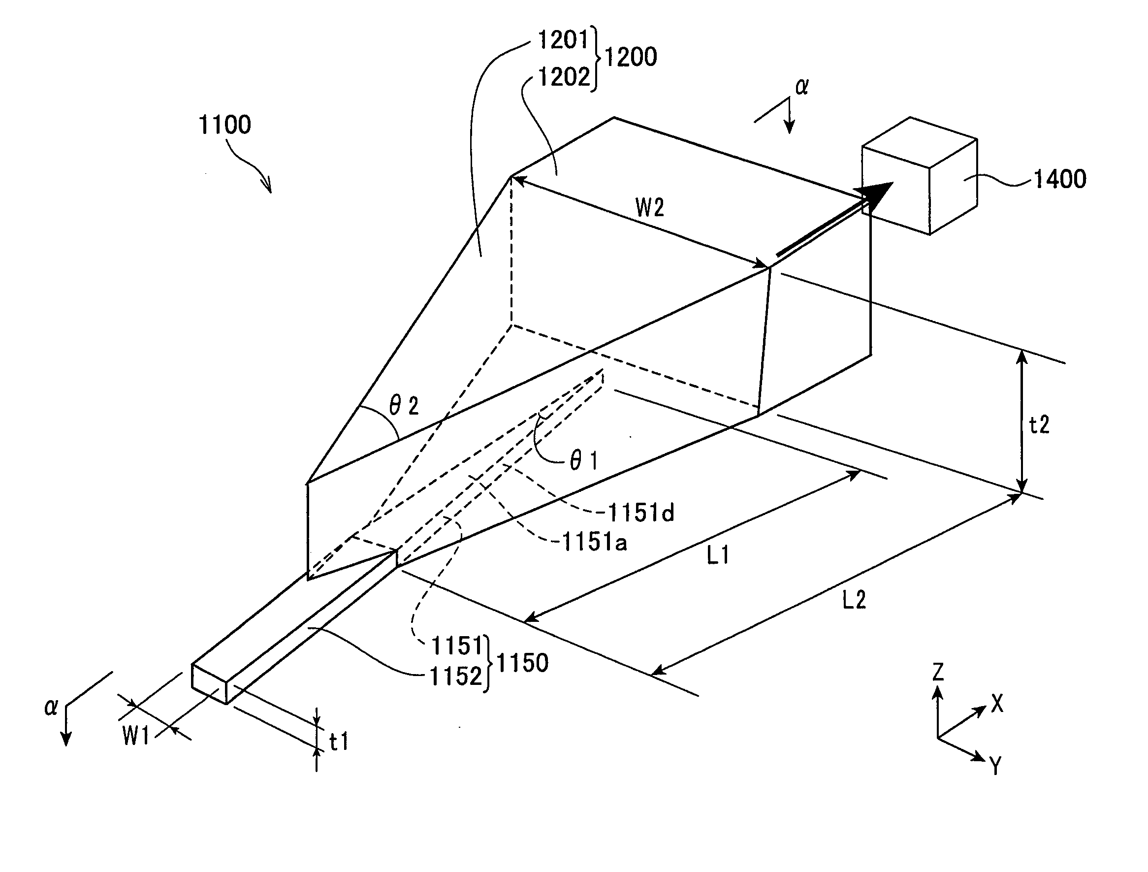
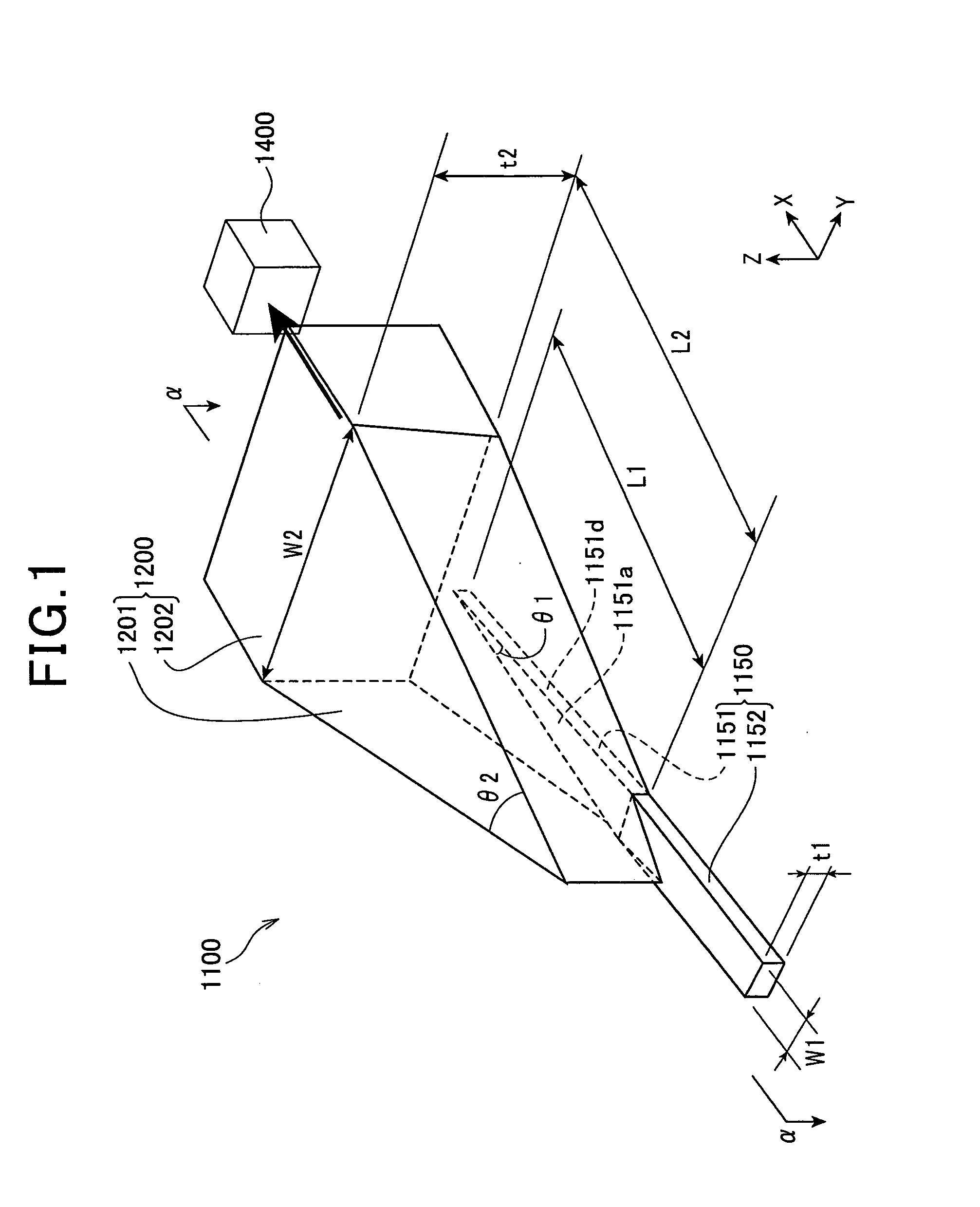
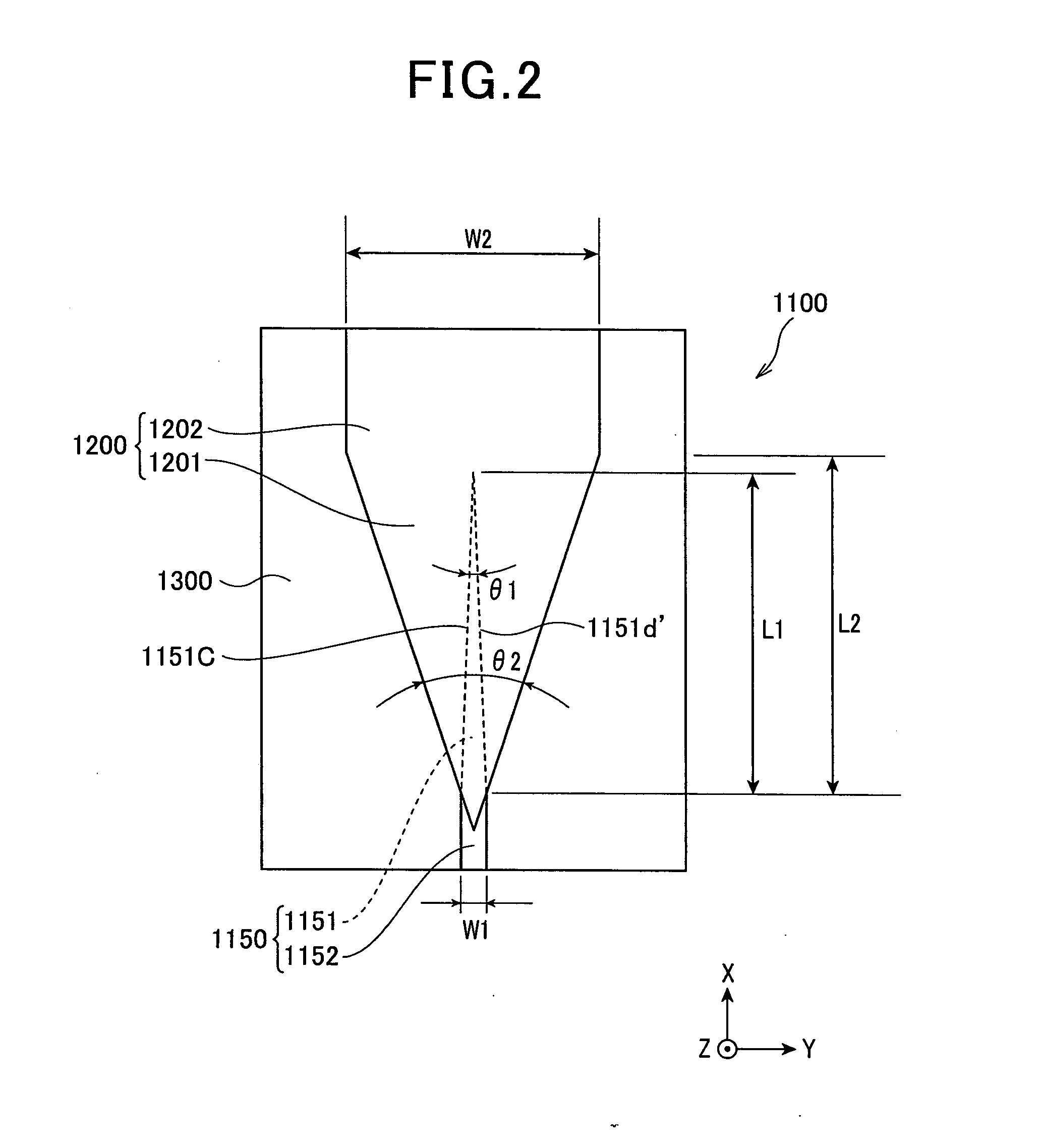
[0187]In a comparison of a sample of the present invention having a form of the spot size converter of the present invention as illustrated in FIG. 1˜FIG. 3 with a comparative sample having an embodiment of a spot size converter of a comparative example as illustrated in FIG. 17 and FIG. 18 (the second core 1900 illustrated in FIG. 17 and FIG. 18 does not has a triangular plate-like taper portion, but has a square column shape), a graph showing the relationship between a taper length (μm) and a propagative efficiency was obtained by simulation experiments. Herein, the taper length is defined with length L2 of the triangular plate-like taper portion of the second core in FIG. 1 and length L1 of the tapered coupling part of the first core. The simulation is under a condition where the length L1=L2.

[0188]The details to each specification are given below.

The following illustrates an experimental example analyzed through simulation.

[0189]Second core material: SiON...

second experiment

[0208](Second Experiment)

[0209]In the configuration of the sample of the present invention according to the aforementioned first experiment, in other words, with the spot size converter of the present invention as illustrated in FIG. 1 through FIG. 3, a simulation experiment was performed to evaluate how the ratio between the length L2 of the triangular plate-like taper portion of the second core and the length L1 of the tapered coupling part of the first core effects waveguide efficiency.

[0210]The basic specification was set in accordance with the aforementioned first experiment. It is noted that L1 was fixed at 230 μm, and the L2 / L1 ratio was varied by changing L2 as illustrated in the following Table 2 in relation to the length of L1 of the fixed numerical value, and that the standardized propagative efficiency was determined corresponding to the change ratio.

[0211]In order to easily visualize the results of Table 2, the results are shown in the graph in FIG. 16. Moreover, the da...


PUM

PropertyMeasurementUnit
Widthaaaaaaaaaa
Widthaaaaaaaaaa
Widthaaaaaaaaaa

Abstract

A spot size converter according to the present invention is capable of shortening the waveguide length in the spot size converter and of promoting a size reduction of the optical waveguide itself because two cores having a taper portion are combined and those tapering angles are mutually aligned. Furthermore, spot size conversion efficiency is favorable even in a small size.

Description

BACKGROUND OF THE INVENTION[0001]1. Field of the Invention[0002]The present invention relates to a spot size converter and thermal assist magnetic recording head (or thermally-assisted magnetic recording head) that uses same.[0003]2. Description of Related Art[0004]Further improvement to thin film magnetic heads and magnetic recording media is in demand in conjunction with the promotion of high recording density in magnetic disk devices in the field of magnetic recording using a head and medium. At the present time, composite type thin film magnetic heads, comprising a structure where a magnetoresistive (MR) element for reading and an electromagnetic conversion element for writing are laminated, are widely used as thin film magnetic heads.[0005]Meanwhile, a magnetic recording medium is a so-called discontinuous body on which magnetic microparticles aggregate, and each of the magnetic microparticles is a single magnetic domain structure. Here, a single recording bit is configured fro...

Claims


Application Information

Patent Timeline
Patent Type & Authority Applications(United States)
IPC IPC(8): G11B5/02G02B6/26G02B6/036
CPCB82Y20/00G02B6/1226G02B6/1228G11B2005/0021G11B5/6088G11B2005/001G11B5/314
Inventor KOMURA, EIJICHOU, TSUTOMUSHIMAZAWA, KOJITAKAYAMA, SEIICHI
Owner TDK CORPARATION
Why Eureka
Try Eureka