
Double-face heat removal of vertically integrated chip-stacks utilizing combined symmetric silicon carrier fluid cavity and micro-channel cold plate

a silicon carrier fluid cavity and vertical integration technology, applied in the field of electrical and thermal arts, can solve the problems of difficult implementation, limited interlayer cooling, and a possible single chip package similar to conventional single-chip packages, and achieve the effect of making the action easier

Active Publication Date: 2011-08-25
GLOBALFOUNDRIES US INC
View PDF20 Cites 57 Cited by
  • Summary
  • Abstract
  • Description
  • Claims
  • Application Information

AI Technical Summary

Benefits of technology

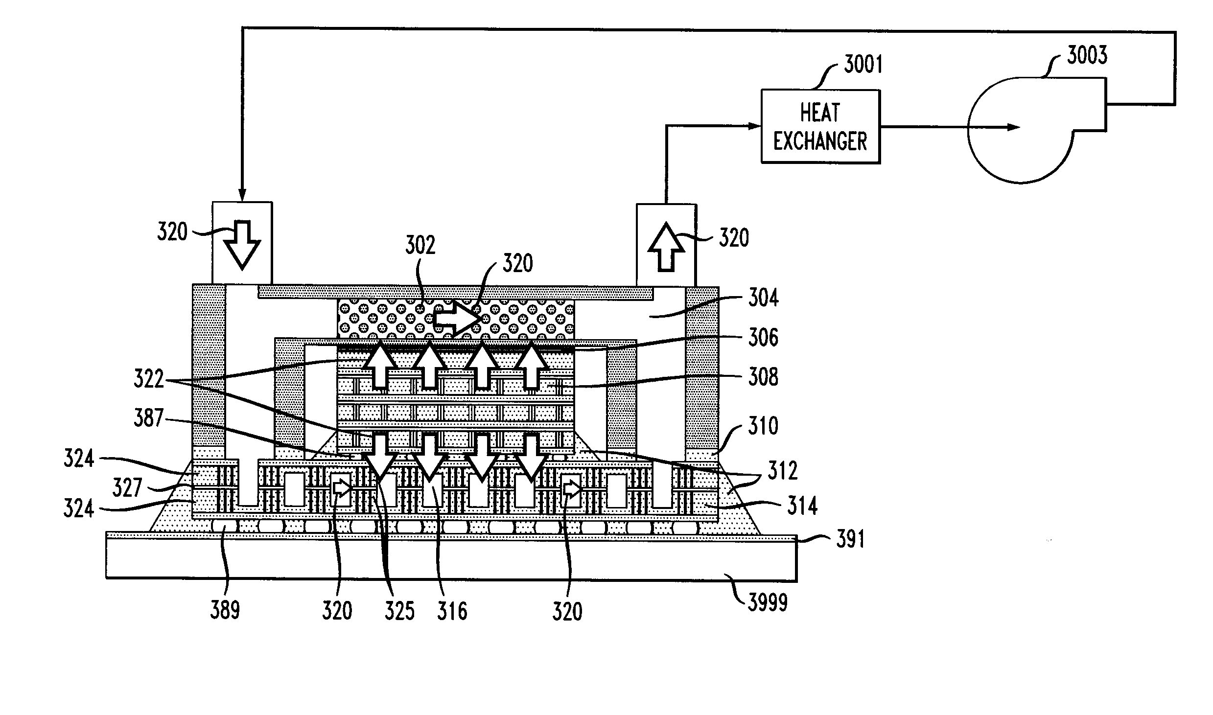
The present invention provides techniques for double-face heat removal of vertically integrated chip-Stacks utilizing a combined symmetric silicon carrier fluid cavity and micro-channel cold plate. The invention involves a plurality of heat-dissipating electronic chips arranged in a vertical chip stack, with a cold plate secured to the back side of the chip stack, a silicon carrier sandwich, defining a fluid cavity, secured to the front side of the chip stack, an inlet manifold in fluid communication with the cold plate and the fluid cavity of the silicon carrier sandwich, and an outlet manifold in fluid communication with the cooling fluid from the cold plate and the fluid cavity of the silicon carrier sandwich. The cold plate, the silicon carrier sandwich, the inlet manifold, and the outlet manifold are configured and dimensioned to electrically isolate the cooling fluid from the electronic components. The technical effects of the invention include improved cooling efficiency, reduced cooling time, and improved electronic component reliability.

Problems solved by technology

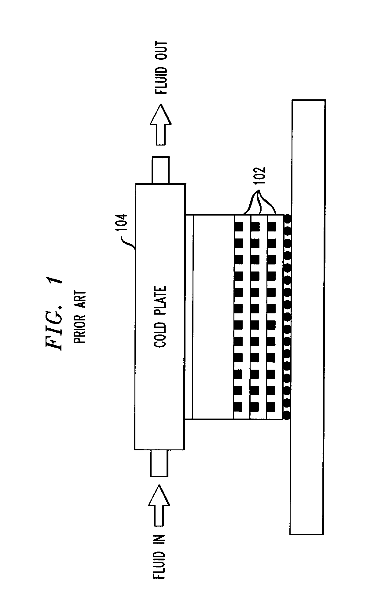
A major challenge in vertically integrated high-performance chip stack packages is their thermal management.
Back-side heat removal with attached air cooled heat sinks or high performance micro-channel cold plates 104 similar to conventional single chip packages is possible but very limited.
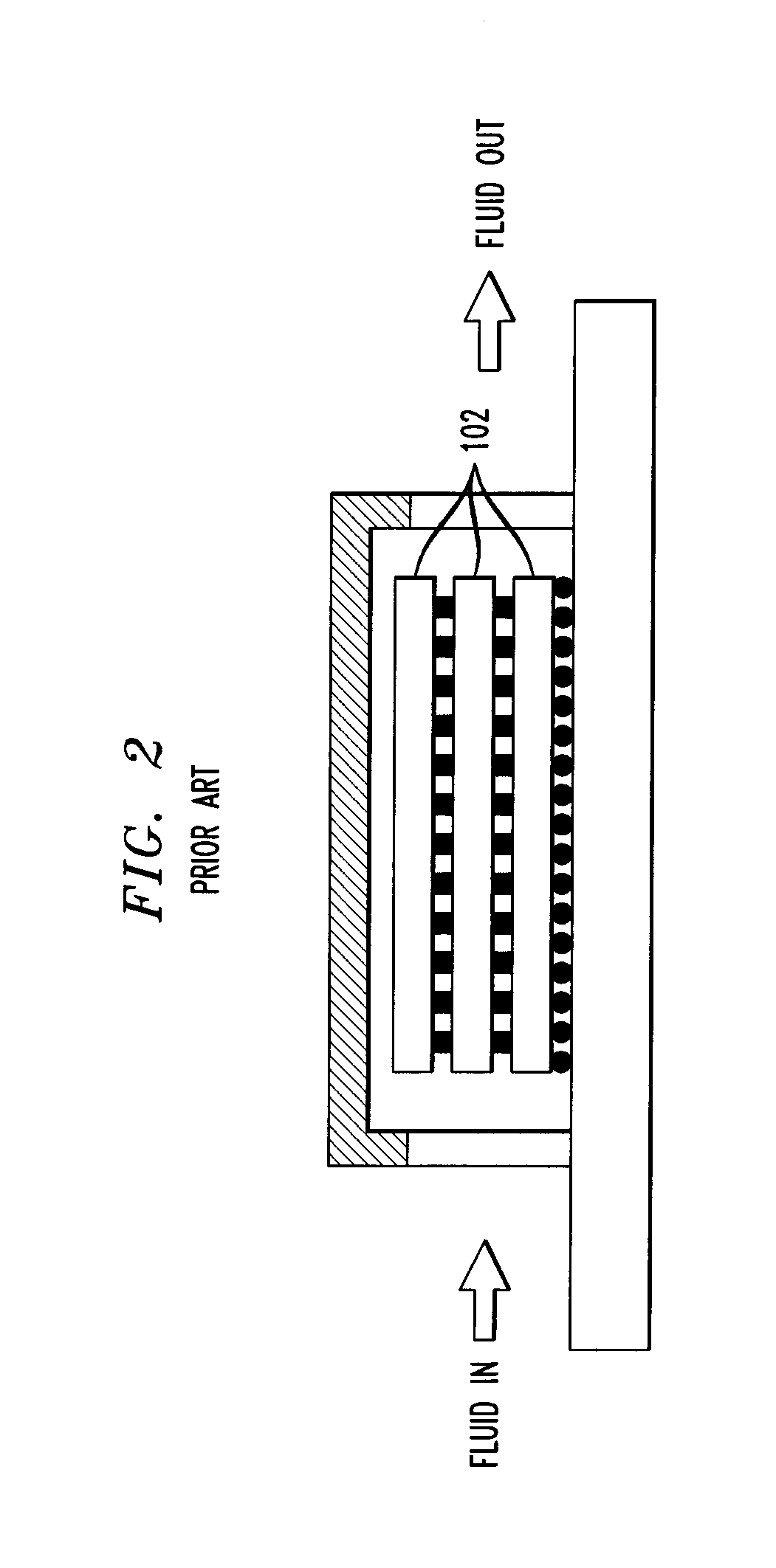
Referring now to FIG. 2, interlayer-cooling is another cooling technology, which does scale with the number of tiers 102, but is very challenging to implement.
Furthermore, interlayer-cooling limits the possible interconnect density to a 50 micron pitch or more for large chips.

Method used


Image

  • Double-face heat removal of vertically integrated chip-stacks utilizing combined symmetric silicon carrier fluid cavity and micro-channel cold plate
  • Double-face heat removal of vertically integrated chip-stacks utilizing combined symmetric silicon carrier fluid cavity and micro-channel cold plate
  • Double-face heat removal of vertically integrated chip-stacks utilizing combined symmetric silicon carrier fluid cavity and micro-channel cold plate

Examples


Embodiment Construction

[0016]One or more embodiments of the invention provide double-face stack cooling utilizing the silicon-carrier and a back-side cold plate as heat absorbers, advantageously combining the strength of the mentioned technologies at moderate complexity. Front-side cooling using dielectric fluids pumped through the C4 (Controlled Collapse Chip Connection) ball array has already been proposed. However, limited heat removal capability is attained due to the poor thermo-physical properties of these coolants, especially in low height cavities, resulting in low heat flux capacity. The use of the superior thermal properties of water was not possible due to electro corrosion and shorting between solder balls. With the symmetric silicon-carrier fluid cavity, according to one or more embodiments of the invention, the electrical inputs and outputs (I / Os) are insulated from the coolant, and therefore water can be used. The industry calls these electrical interconnects “through silicon vias” (TSV).

[0...


PUM


Abstract

A plurality of heat-dissipating electronic chips are arranged in a vertical chip stack. The electronic chips have electronic components thereon. A cold plate is secured to a back side of the chip stack. A silicon carrier sandwich, defining a fluid cavity, is secured to a front side of the chip stack. An inlet manifold is configured to supply cooling fluid to the cold plate and the fluid cavity of the silicon carrier sandwich. An outlet manifold is configured to receive the cooling fluid from the cold plate and the fluid cavity of the silicon carrier sandwich. The cold plate, the silicon carrier sandwich, the inlet manifold, and the outlet manifold are configured and dimensioned to electrically isolate the cooling fluid from the electronic components. A method of operating an electronic apparatus and a method of manufacturing an electronic apparatus are also disclosed. Single-sided heat removal with double-sided electrical input-output and double-sided heat removal with double-sided electrical input-output are also disclosed.

Description

FIELD OF THE INVENTION[0001]The present invention relates to the electronic and thermal arts, and, more particularly, to thermal control of electronics.BACKGROUND OF THE INVENTION[0002]A major challenge in vertically integrated high-performance chip stack packages is their thermal management. With reference to FIG. 1, the heat flux and thermal resistance accumulate with each additional tier, or chip layer 102. Back-side heat removal with attached air cooled heat sinks or high performance micro-channel cold plates 104 similar to conventional single chip packages is possible but very limited. This is because their heat removal capability does not scale with the number of stacked dies 102 and therefore limits the possible heat flux and the number of tiers 102 in the stack. Referring now to FIG. 2, interlayer-cooling is another cooling technology, which does scale with the number of tiers 102, but is very challenging to implement. Furthermore, interlayer-cooling limits the possible inte...

Claims


Application Information

Patent Timeline
Patent Type & Authority Applications(United States)
IPC IPC(8): H05K7/20H01L21/50
CPCH01L23/147H01L2224/16225H01L23/473H01L23/481H01L23/49827H01L25/0657H01L2225/06513H01L2225/06517H01L2225/06541H01L2225/06589H01L2224/16227H01L2924/15311H01L2924/10253H01L23/3677H01L2924/00H01L2924/00014H01L2224/0401H05K7/20
Inventor ANDRY, PAUL S.BRUNSCHWILER, THOMAS J.COLGAN, EVAN G.MAGERLEIN, JOHN H.
Owner GLOBALFOUNDRIES US INC
Learn More