System, apparatus, and method to indicate preferred access points and service providers

a technology of applied in the field of system, apparatus, and method to indicate preferred access points and service providers, can solve the problems of not providing enough information, and achieve the effects of improving qos, improving cost/value, and increasing access

Active Publication Date: 2011-08-25
NETWORK SYST TECH LLC +1
View PDF12 Cites 47 Cited by
  • Summary
  • Abstract
  • Description
  • Claims
  • Application Information

AI Technical Summary

Benefits of technology

[0009]For roaming, the present invention reduces the delay in this discovery phase and contributes to a decrease in the overall roaming delay, avoiding packet loss and waste of energy by the STAs. Therefore, mechanisms to minimize the discovery delay are a key feature of the present invention and contribute to optimizing roaming performance. Furthermore, the present invention takes network load considerations and QoS requirements into account by preferring for a STA to roam to a neighbor AP that is able to better support the QoS requirements.
[0010]The currently available mechanisms for minimizing discovery delay include channel lists and neighbor lists that do not allow a STA to differentiate between candidates, nor do these existing mechanisms provide enough information for the STAs to decide which is the best candidate AP or which AP to associate with first. The best channel and / or AP candidate for a given STA depends on several factors, such as relative position between the STA and the currently available APs and traffic load at the currently available APs, and this information is provided and used by the present invention so that an AP provides an indication of the channel and / or AP that is more appropriate for roaming at a given location and time.
[0016]With the priority indicated by an AP for SPs, a STA then tries to establish a connection with an SP having a highest indicated priority first, although the STA ultimately determines how to take into account the priorities provided by the AP when establishing a connection to an SP. Therefore, the AP and STA both gain by establishing a connection to the preferable SPs. A STA gains by having more access to the services, better QoS, better cost / value, better chance of admission, reliable / guaranteed service etc. An AP gains by having more STAs using services that it is better equipped to handle, has more profit potential, provides more user satisfaction, provides better QoS, etc.

Problems solved by technology

The currently available mechanisms for minimizing discovery delay include channel lists and neighbor lists that do not allow a STA to differentiate between candidates, nor do these existing mechanisms provide enough information for the STAs to decide which is the best candidate AP or which AP to associate with first.

Method used


Image

  • System, apparatus, and method to indicate preferred access points and service providers
  • System, apparatus, and method to indicate preferred access points and service providers
  • System, apparatus, and method to indicate preferred access points and service providers

Examples


first embodiment

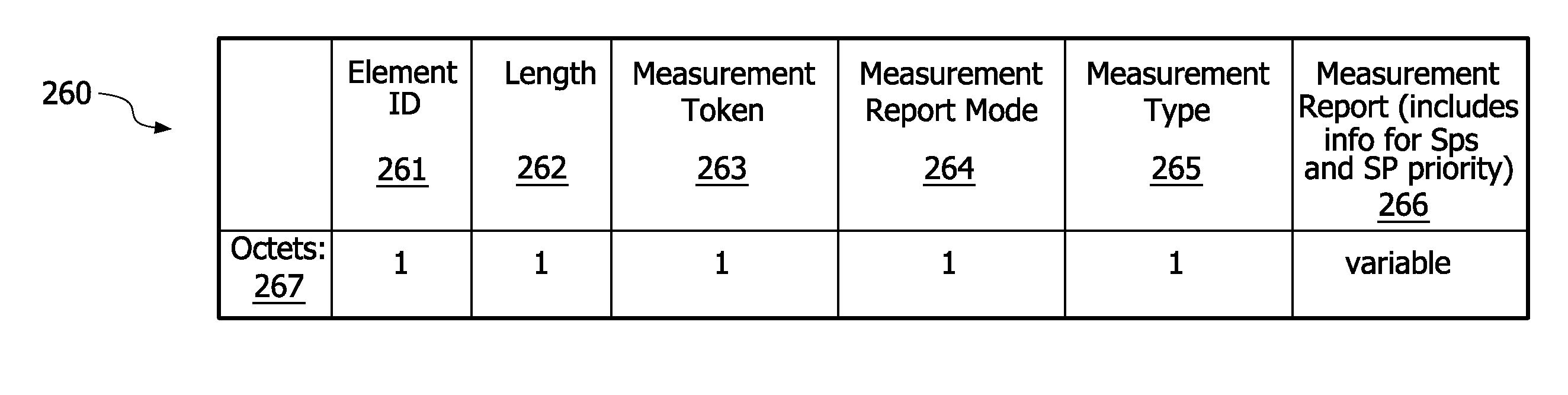
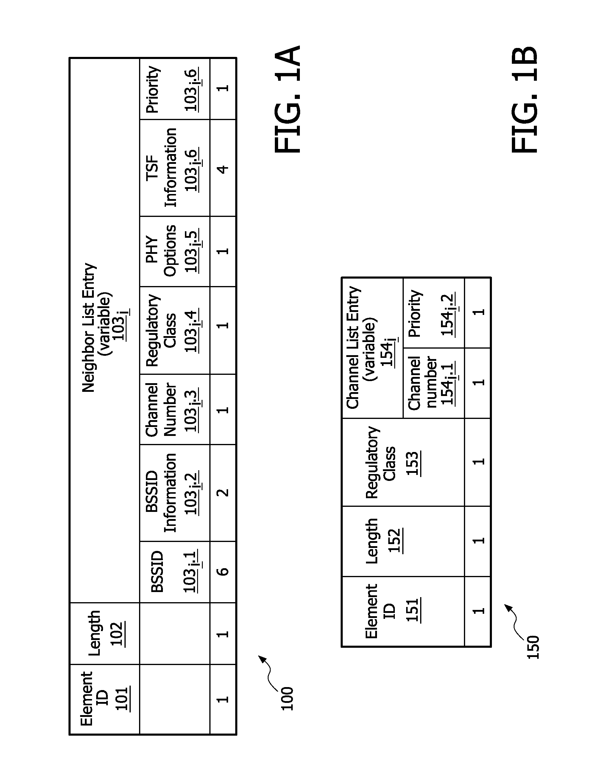
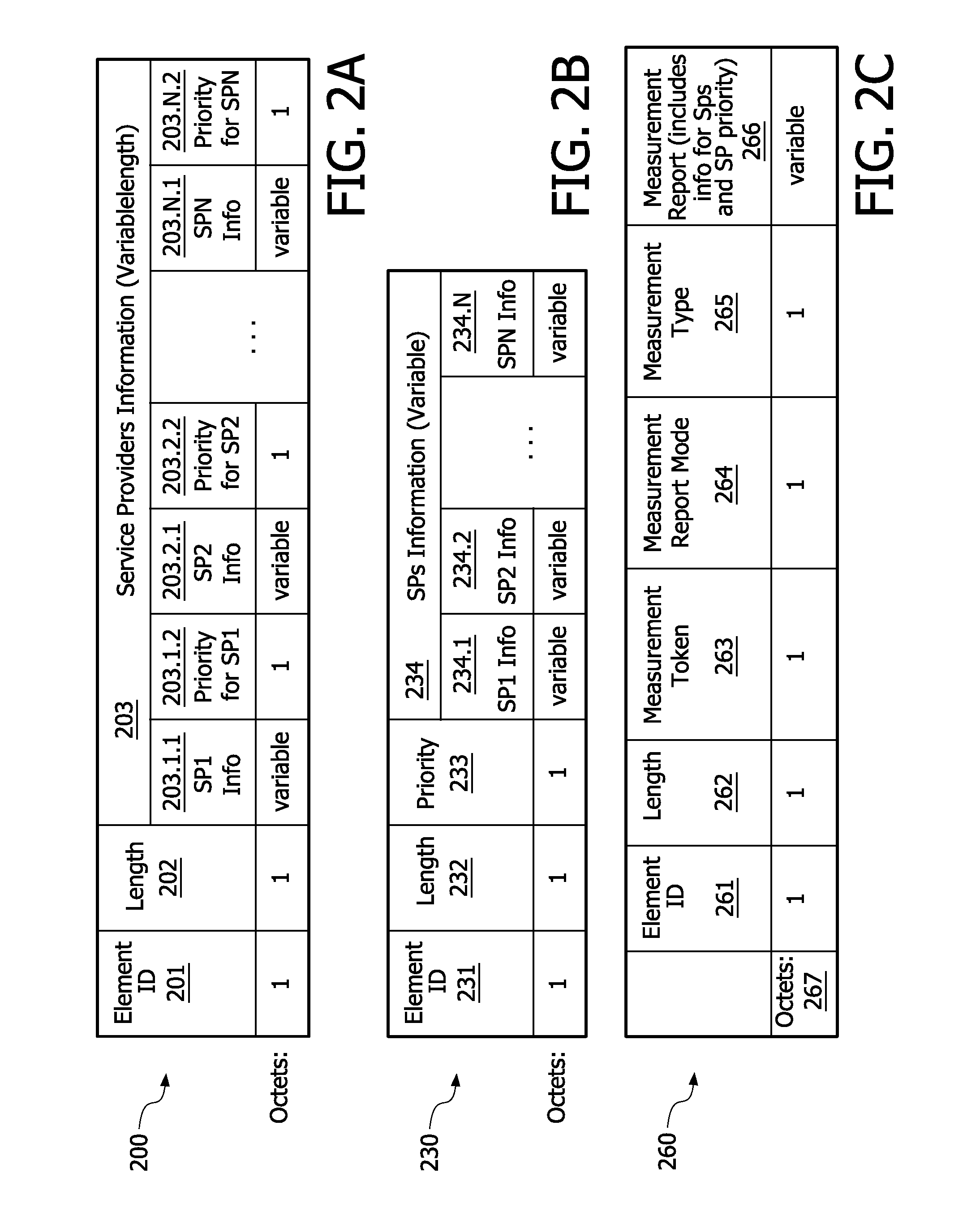
[0032]The system, apparatus, and method of the present invention provide a “Priority” field having a priority value in information transmitted by an AP about its neighboring APs and / or service providers (SPs). In a first embodiment, referring to FIGS. 1A and 1B, a respective “Priority” field 102.6 and 154.2 is included in a Neighbor Report element 100 and AP Channel Report element 150. The “Priority” field preferably contains a numeric or symbolic value indicating a recommendation from the transmitting AP to a receiving STA about which AP / APs to scan first in an eventual roaming process. More than one AP may have the same priority value and not all the APs necessarily have the same priority value.

[0033]In a preferred first embodiment an AP generates these priority values based on the load information of the neighbor APs, location of the requesting STA, ability of the APs to accept new connections and to accept connections with QoS requirements, among other parameters.

[0034]Given the...

second embodiment

[0042]As shown in FIG. 2A, a priority field 203.i.2 is associated with each SP in the Information Element 200. In this second embodiment, the priority field 203.i.2 is left ‘undefined’ whenever the priority of an SP cannot be established or if it desired not to populate the priority field. In a preferred embodiment, the priority field length of the Information Element 200 is selected from the group consisting of a 1-octet length field, as indicated in FIG. 2A, and a length denoted by S>1-octect, which is configured by a network operator.

[0043]Referring now toFIG. 2B, in an alternative second embodiment, the priority information 233 is associated with multiple SPs such that an AP uses a single priority field 233 to indicate its preference with respect to several SPs. In this alternative, the Information Element 230 shown in FIG. 2B includes a single priority field 231. The single priority field 233 depicted in FIG. 2B can represent a priority threshold for all SPs included in the Inf...


PUM


Abstract

The present invention is a system, apparatus, and method for a “Priority” field that is included in the information transmitted by an Access Point (AP) (801i) about its neighbor APs (801i) and the network service providers (SPs) that it supports. A “Priority” field (103i-6 154i.2 203.i.2 233 266) is included in at least one of a Neighbor Report element (100), an AP Channel Report element (150), and a service provider's information element (200 230 260). The service provider priority field (203.i.2 233 266) is contained in any protocol frame transmitted by the AP (801i) that contains information about one or more service providers that it supports. The “Priority” field (103i.6 154-i.2 203.i.2 233 266) contains a numeric value or a symbolic indicating a recommendation from the AP (801i) concerning which AP / APs and service provider(s) SP / SPs for a STA (802j) to scan first or access in an eventual roaming / accessing process. For roaming / accessing purposes, more than one neighboring AP (801i) can have the same priority value and not all the APs (801i) that are neighbors or support SPs necessarily have the same priority value.

Description

FIELD OF THE INVENTION[0001]The present invention relates to a system, apparatus and method for prioritizing access points (APs) and / or service providers (SPs) for preferred connectivity thereto by a station (STA) in a wireless network.BACKGROUND OF THE INVENTION[0002]The support of access to STA-selected APs is a general requirement in any wireless system where the mobile stations access the network through APs or base stations, and for many real time based applications, any delay in the access process may degrade the quality of the service. The problem of minimizing the access delay remains a major challenge for most wireless system designers. One of the main issues is the limited ability of the mobile stations in discovering and maintaining network state information for use in optimization of the AP selection procedure. This problem is compounded by the STAs' need to have information about the service providers supported by an AP and / or neighboring APs in choosing an AP to access...

Claims


Application Information

Patent Timeline
Patent Type & Authority Applications(United States)
IPC IPC(8): H04W36/08H04W24/10
CPCH04W48/08H04W48/16H04W80/04H04W64/00H04W48/20H04W24/10
Inventor SOOMRO, AMJADCAVALCANTI, DAVE A.T.
Owner NETWORK SYST TECH LLC
Why Eureka
Try Eureka