Tracked cartilage repair system

a cartilage repair and cartilage technology, applied in the field of tissue repair and replacement, can solve the problems of pain and/or restricted mobility, damage to anatomical tissues, and bone and cartilage damage,

Active Publication Date: 2011-08-25
ZIMMER INC
View PDF52 Cites 89 Cited by
  • Summary
  • Abstract
  • Description
  • Claims
  • Application Information

AI Technical Summary

Benefits of technology

[0008]The present disclosure provides a system and method for repairing an area of defective tissue which reduces the removal of healthy tissue at the margins of the defect. During excision of diseased or damaged tissue, the system tracks the movement and function of a tissue resection tool within a monitored surgical space. This movement is continuously recorded to create a three-dimensional set of data points representative of the excised volume of tissue. This data set is then communicated to a custom implant forming device which creates a custom implant sized to fit the void created by the excision. The system and method of the present disclosure allows a surgeon to exercise intraoperative control over the specific shape, volume and geometry of the excised area. Moreover, the surgeon may utilize a “freehand” resection method to excise only that tissue deemed to be diseased and / or damaged, because the custom-formed implant will accommodate an irregularly-shaped resection volume.

Problems solved by technology

Damage to anatomical tissues, i.e. bone and cartilage, may result from trauma, aging or disease, for example.
Such damage may result in pain and / or restricted mobility, which in turn may necessitate surgical intervention to repair the damaged tissues.
However, some anatomical tissues may require lengthy periods of time to heal or may have limited capability to heal on their own.
However, use of this method for elongate defects, such as hairline fractures or irregularly shaped diseased tissue profiles, may result in the removal of a large proportion of healthy tissue material.

Method used


Image

  • Tracked cartilage repair system
  • Tracked cartilage repair system
  • Tracked cartilage repair system

Examples


Embodiment Construction

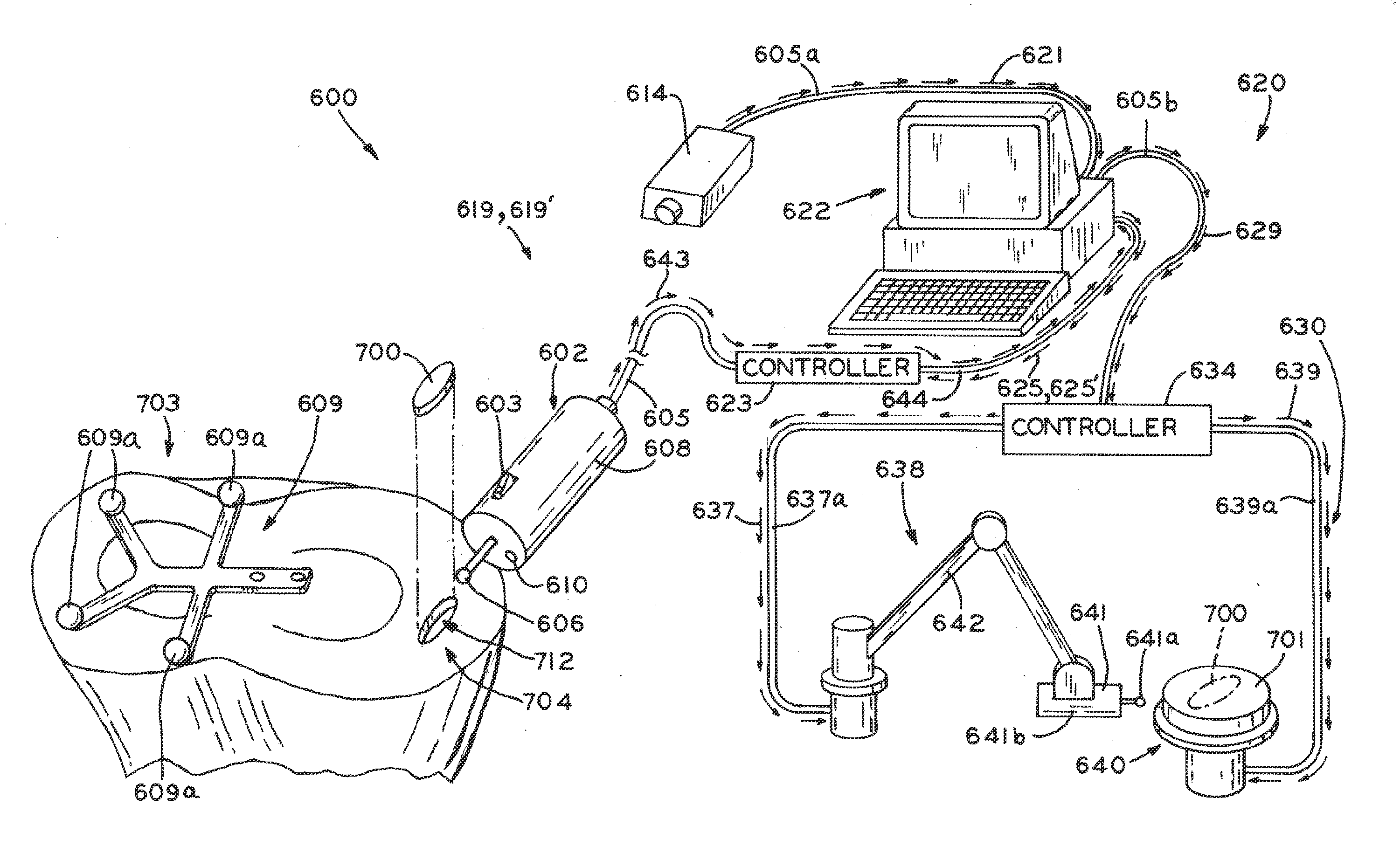
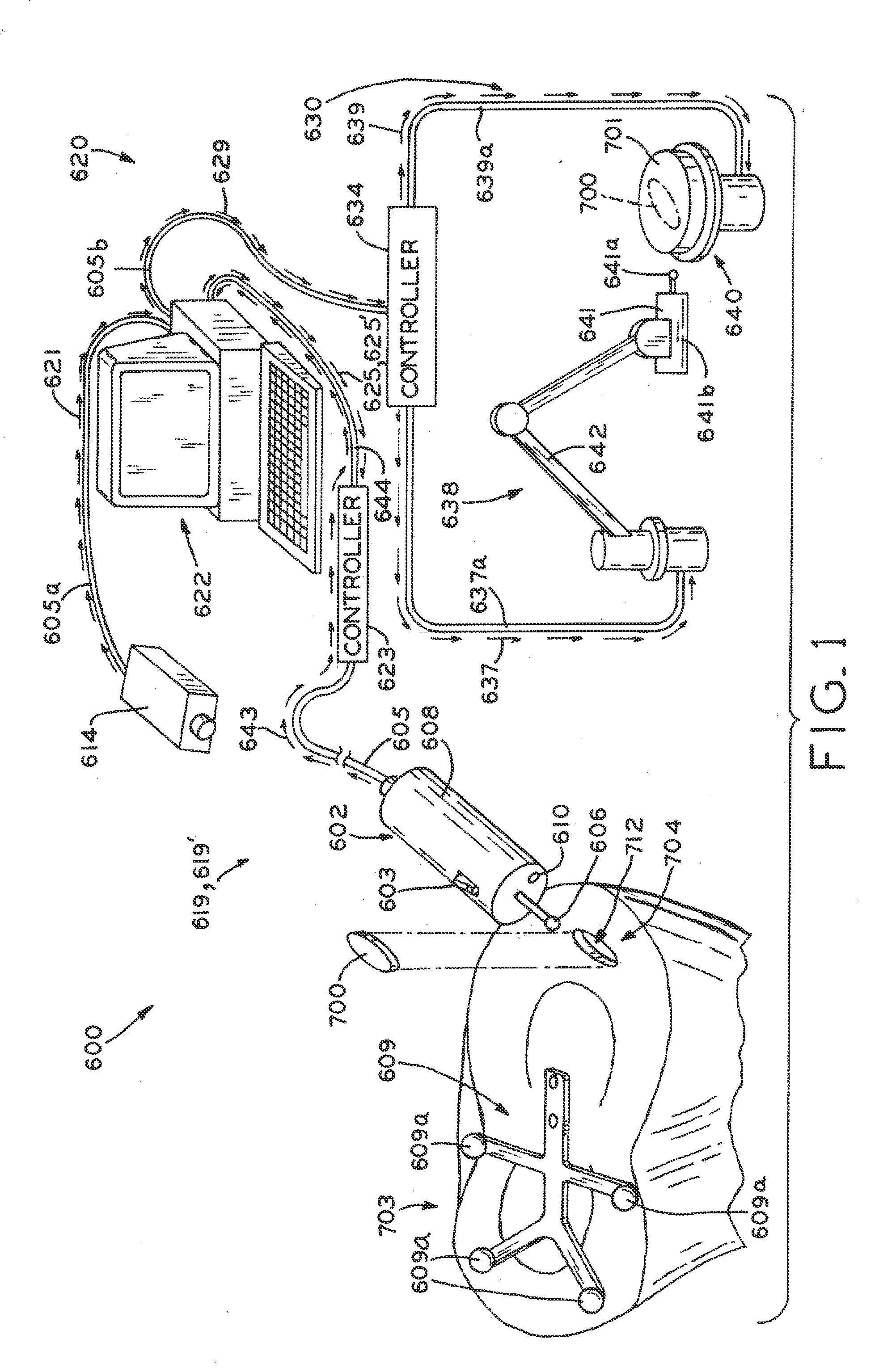
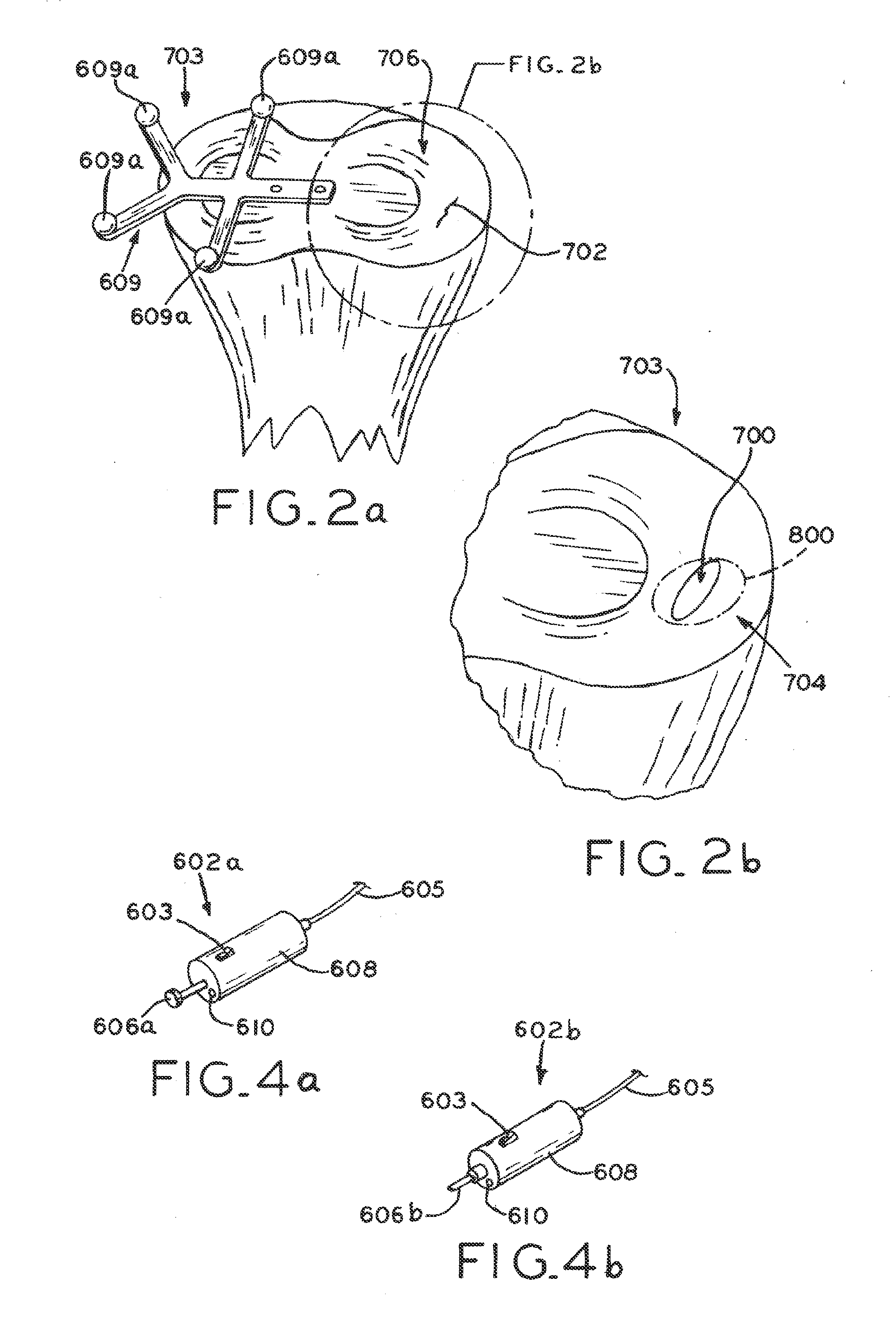
[0026]Referring to FIG. 1, orthopaedic system 600 includes tracked tissue resection tool 602, tracking system 619, signal conversion system 620, and custom implant forming system 630. As resection tool 602 is used to resect defective tissue 702 (FIG. 2a), tracking system 619 monitors the movement of tool 602. Data points indicative of the monitored cutter position are collected throughout the resection, rendering a set or “cloud” of data points bounding a virtual volume that is representative of void 712. Tracking system 619 sends this data set to signal conversion system 620, which in turn converts the data into implant forming commands 629. Implant forming commands 629 are then sent to implant forming system 630, which creates custom implant 700 sized and shaped to fill void 712 created by the resection of defective tissue 702.

[0027]In the illustrated embodiment, orthopaedic system 600 is used to repair defect 702 (FIG. 2a) located in tissue 704 at the proximal end of tibia 703. H...


PUM

PropertyMeasurementUnit
volumeaaaaaaaaaa
degrees of freedomaaaaaaaaaa
anatomical structureaaaaaaaaaa

Abstract

A system and method for repairing an area of defective tissue reduces the removal of healthy tissue at the margins of the defect. During excision of diseased or damaged tissue, the system tracks the movement and function of a tissue resection tool within a monitored surgical space. This movement is continuously recorded to create a three-dimensional set of data points representative of the excised volume of tissue. This data set is then communicated to a custom implant forming device which creates a custom implant sized to fit the void created by the excision. The system and method of the present disclosure allows a surgeon to exercise intraoperative control over the specific shape, volume and geometry of the excised area. Moreover, the surgeon may utilize a “freehand” resection method to excise only that tissue deemed to be diseased and/or damaged, because the custom-formed implant will accommodate an irregularly-shaped resection volume.

Description

CROSS REFERENCE TO RELATED APPLICATIONS[0001]This application claims the benefit under 35 U.S.C. §119(e) of U.S. Provisional Patent Application Ser. No. 61 / 308,176, filed Feb. 25, 2010, the entire disclosure of which is hereby expressly incorporated herein by reference.BACKGROUND[0002]1. Technical Field[0003]The present disclosure relates to tissue repair and replacement. More particularly, the present disclosure relates to a surgical system for repairing a tissue defect and a method for utilizing the same.[0004]2. Description of the Related Art[0005]Damage to anatomical tissues, i.e. bone and cartilage, may result from trauma, aging or disease, for example. Such damage may result in pain and / or restricted mobility, which in turn may necessitate surgical intervention to repair the damaged tissues. However, some anatomical tissues may require lengthy periods of time to heal or may have limited capability to heal on their own.[0006]Various techniques have been developed to repair tiss...

Claims


Application Information

Patent Timeline
Patent Type & Authority Applications(United States)
IPC IPC(8): A61B17/56B26D1/12
CPCA61B17/16A61B17/32002A61B19/44A61B19/50A61F2/30942A61B2019/448A61B2019/502A61F2/30756A61B19/5244A61B34/10A61B34/20A61B90/90A61B90/98A61B2034/102B33Y80/00Y10T83/9372A61B2034/108A61B2034/2072
Inventor ZUHARS, JOEL
Owner ZIMMER INC
Why Eureka
Try Eureka