Micro-optic security and image presentation system presenting a synthetically magnified image that appears to lie above a given plane

a micro-optic and image technology, applied in the field of synthetic magnification microoptic systems, can solve the problems of fuzzy images, unsuitable for document authentication, and relatively thick structure of the approach all suffering from similar drawbacks

Active Publication Date: 2011-09-01
VISUAL PHYSICS LLC (US)
View PDF99 Cites 55 Cited by
  • Summary
  • Abstract
  • Description
  • Claims
  • Application Information

AI Technical Summary

Benefits of technology

[0034]Also provided is a security document or label having at least one security device, as defined above, at least partially embedded therein and / or mounted thereon.
[0037]Unless otherwise defined, all technical and scientific terms used herein have the same meaning as commonly understood by one of ordinary skill in the art to which this invention belongs. All publications, patent applications, patents and other references mentioned herein are incorporated by reference in their entirety. In case of conflict, the present specification, including definitions, will control. In addition, the materials, methods, and examples are illustrative only and not intended to be limiting.

Problems solved by technology

These approaches all suffer from similar drawbacks.
They result in a relatively thick structure that is not particularly suitable for use with document authentication.
Their use of cylindrical or spherical lenses provides a narrow field of view resulting in fuzzy images and requiring exact and difficult alignment of the focal point of the lenses with the associated images.
Additionally, they have not proven particularly effective as security or anti-counterfeiting measures.

Method used


Image

  • Micro-optic security and image presentation system presenting a synthetically magnified image that appears to lie above a given plane
  • Micro-optic security and image presentation system presenting a synthetically magnified image that appears to lie above a given plane
  • Micro-optic security and image presentation system presenting a synthetically magnified image that appears to lie above a given plane

Examples


embodiment 272

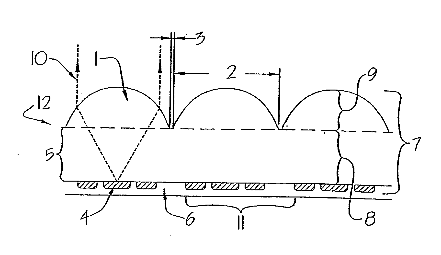
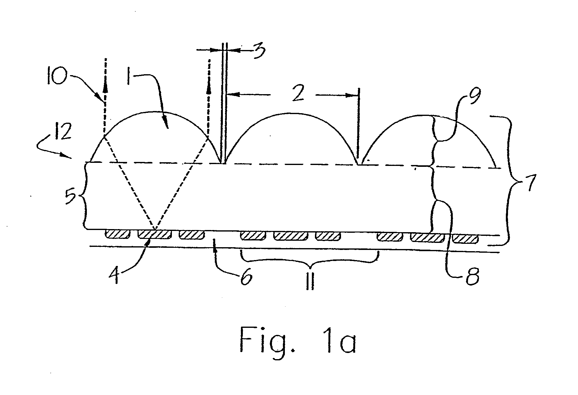
[0135]FIG. 15b illustrates another two-sided embodiment 272 having two icon planes 276 and 278 that are imaged, 282 and 286 respectively, by two sets of lenses, 274 and 280 respectively. This embodiment is essentially two separate systems, 287 and 289, such as illustrated in FIG. 1a, that have been joined together with an icon layer spacer 277 in between them. The thickness of this icon layer spacer 277 will determine the degree that the ‘wrong’ icon layer is imaged 284 and 288 by a set of lenses. For example, if the thickness of icon layer spacer 277 is zero, such that icon layers 276 and 278 are in contact, then both icon layers will be imaged by both sets of lenses 274 and 280. In another example, if the thickness of icon layer spacer 277 is substantially larger than the depth of focus of lenses 274 and 280, then the ‘wrong’ icon layers will not be imaged by the lenses 274 and 280. In yet another example, if the depth of focus of one set of lenses 274 is large, but the depth of f...

embodiment 326

[0142]FIGS. 16d, e disclose another embodiment 326 of transparent bas-relief micro structured icon layer 311 including icon elements 329 and 331 that are coated with a high refractive index material 328. The icon layer 311 can be sealed with an optional sealing layer 321 that fills the icon elements 329 and 331, 330 and 332, respectively. The high refractive index layer 328 enhances the visibility of sloping surfaces by creating reflections from them by total internal reflection. Plan views 342 and 344 present representative images of the appearance of icon elements 329 and 331 and their synthetically magnified images. This high refractive index coating embodiment provides a kind of edge-enhancement effect without adding pigment or dye to make the icons and their images visible.

[0143]FIG. 16f discloses yet another embodiment 333 of transparent bas-relief micro structured icon 335 utilizing an air, gas, or liquid volume 336 to provide visual definition for this phase interface 334 mi...


PUM

PropertyMeasurementUnit
diameteraaaaaaaaaa
thicknessaaaaaaaaaa
focal lengthaaaaaaaaaa

Abstract

A film material utilizing a regular two-dimensional array of non-cylindrical lenses to enlarge micro-images, called icons, to form a synthetically magnified image through the united performance of a multiplicity of individual lens / icon image systems. The synthetic magnification micro-optic system includes one or more optical spacers (5), a micro-image formed of a periodic planar array of a plurality of image icons (4) having an axis of symmetry about at least one of its planar axes and positioned on or next to the optical spacer (5), and a periodic planar array of image icon focusing elements (1) having an axis of symmetry about at least one of its planar axes, the axis of symmetry being the same planar axis as that of the micro-image planar array (4). A number of distinctive visual effects, such as three-dimensional and motion effects, can be provided by the present system.

Description

CROSS-REFERENCE TO RELATED APPLICATIONS[0001]This application is a divisional of U.S. patent application Ser. No. 11 / 932,642, filed Oct. 31, 2007, which is a divisional of U.S. Utility patent application Ser. No. 10 / 995,859, filed Nov. 22, 2004 (now U.S. Pat. No. 7,333,268), and claims benefit of and priority to U.S. Provisional Patent Application Ser. No. 60 / 524,281, filed on Nov. 21, 2003, U.S. Provisional Patent Application Ser. No. 60 / 538,392, filed on Jan. 22, 2004, and U.S. Provisional Patent Application Ser. No. 60 / 627,234, filed on Nov. 12, 2004, and where permissible, each of which is incorporated by reference in their entirety.FIELD OF THE INVENTION[0002]The present invention relates to a synthetic magnification micro-optic system that in an exemplary embodiment is formed as a polymer film. The unusual optical effects provided by the various embodiments of the disclosure can be used as a security device for overt and covert authentication of currency, documents, and produc...

Claims


Application Information

Patent Timeline
Patent Type & Authority Applications(United States)
IPC IPC(8): B23P11/00B42D15/10D21H21/44G02BG02B3/00G02B27/10G02B27/22
CPCB42D2033/24Y10T29/49826B42D2035/20B42D2035/44B44F1/06B44F1/10D21H21/44G02B3/0031G02B3/0043G02B3/0056G02B27/06G02B27/2214B42D25/342B42D25/00B42D2035/08B42D25/324B42D25/351B42D25/36B42D25/364B42D25/369B42D25/373B42D25/378G03H1/00G02B27/10B42D25/29B41M3/148G02B27/1006B41M3/14B42D25/41G02B30/27
Inventor STEENBLIK, RICHARD A.HURT, MARK J.JORDAN, GREGORY R.
Owner VISUAL PHYSICS LLC (US)
Why Eureka
Try Eureka