Solar thermal power generation using multiple working fluids in a rankine cycle

a technology of solar thermal power generation and working fluids, applied in the direction of steam generation using solar heat, machines/engines, transportation and packaging, etc., can solve the problems of reducing cost effectiveness and/or environmental stewardship, affecting so as to improve the economics of solar thermal generation. , the effect of increasing outpu

Active Publication Date: 2011-09-01
TAS ENERGY
View PDF12 Cites 77 Cited by
  • Summary
  • Abstract
  • Description
  • Claims
  • Application Information

AI Technical Summary

Benefits of technology

[0016]Aspects of the invention, as shown in FIGS. 1A and 1B, may combine advantageous attributes of the steam cycle with the ORC. Additionally, the invention improves plant economics by using heat supplied at different temperature levels by designing (or specifying) collectors for their designated temperature duty (i.e., high temperature collectors (HTC) for a steam cycle, and low temperature collectors (LTC) for the ORC). In alternate embodiments, heat sources other than solar collectors may be used. Such alternate heat sources may also be designed for various temperature duties.
[0017]The invention may improve the economics of solar thermal generation by increasing output, and reducing capital cost and operating cost. This may reduce the all-in cost of solar thermal generation as measured in $ / MWh.
[0018]Further, by finding a way to overcome the problem of wet cooling and the large make-up requirements associated with wet cooling, solar thermal generation systems and methods of the present invention can overcome major environmental disadvantages of prior systems and methods.
[0019]The integration of the steam cycle and the ORC, as opposed to using each separately, may provide design flexibility and an additional degree of freedom that may allow the two subsystems to operate more efficiently and at lower cost than two stand-alone units. By “marrying” or combining the steam cycle with the ORC, the best features of each can be achieved and the disadvantages can be avoided.

Problems solved by technology

Thus there appears to be a trade-off between the power plant's thermal efficiency and solar collector efficiency such that moving to higher fluid temperatures may require a larger collector field than otherwise would have been necessary absent this additional loss.
Prior plant designs have several limitations, such as diminished cost effectiveness and / or environmental stewardship.
Cooling by air is very expensive due to the very high specific volume of steam.
Very large pipes and tubes equate to large capital cost.
In a solar plant, particularly those located in the desert, water is scarce.
This is a source of major criticism to those who build solar plants to promote their environmental stewardship.
In years to come, it is expected that water for plant cooling will become even more scarce and expensive.
Another example of a limitation of prior plant designs and methods is how, in a typical concentrating solar trough design, all collectors / receivers are built to supply the same high temperature fluid throughout.
However, as noted above, there is a trade-off between performance and economics.
Condensing steam turbines in the 50 MW class can be very large in diameter (condensing stages can be 7-8 feet in diameter), making them expensive and requiring up to three years of manufacturing lead time (Glen Davis, EVP, Ausra Inc.).
The latter has the effect of adding substantial cost to the project by delaying power production for at least three years from project commencement.
Off-design conditions are another limitation of prior steam plant designs and methods.
Unfortunately, steam plants do not do well in these circumstances.
If steam were admitted to the turbine at part load conditions (lower temperature and pressure) the expansion would result in the formation of moisture (water droplets) in the condensing stages of the turbine which, in turn, would cause erosion damage to the turbine blades (buckets).
Much of the solar energy that reaches the collectors during non-peak periods is not converted to power, resulting in loss of plant revenue.
In some cases this may be mitigated by using natural gas fuel and / or thermal storage to accelerate the warm-up process, but both options may be expensive.
A fully condensing, high temperature steam plant, though having mature technology, is expensive to operate because of the need to keep the water very clean (boiler blow down, de-ionized water, condensate polishing, etc.), free of oxygen (or air), and the need to maintain a deep vacuum at the exit of the turbine.
All this adds complexity, additional operator labor and increases in plant running costs.
However, the ORC has its limitations.
For example, the ORC has a major disadvantage in not being able to achieve the high temperatures found in steam plants.
For instance, at some elevated temperature, the working fluid may decompose and lose the properties of the original fluid.

Method used


Image

  • Solar thermal power generation using multiple working fluids in a rankine cycle
  • Solar thermal power generation using multiple working fluids in a rankine cycle
  • Solar thermal power generation using multiple working fluids in a rankine cycle

Examples


Embodiment Construction

[0030]While preferable embodiments of the invention have been shown and described herein, it will be obvious to those skilled in the art that such embodiments are provided by way of example only. Numerous variations, changes, and substitutions will now occur to those skilled in the art without departing from the invention. It should be understood that various alternatives to the embodiments of the invention described herein may be employed in practicing the invention.

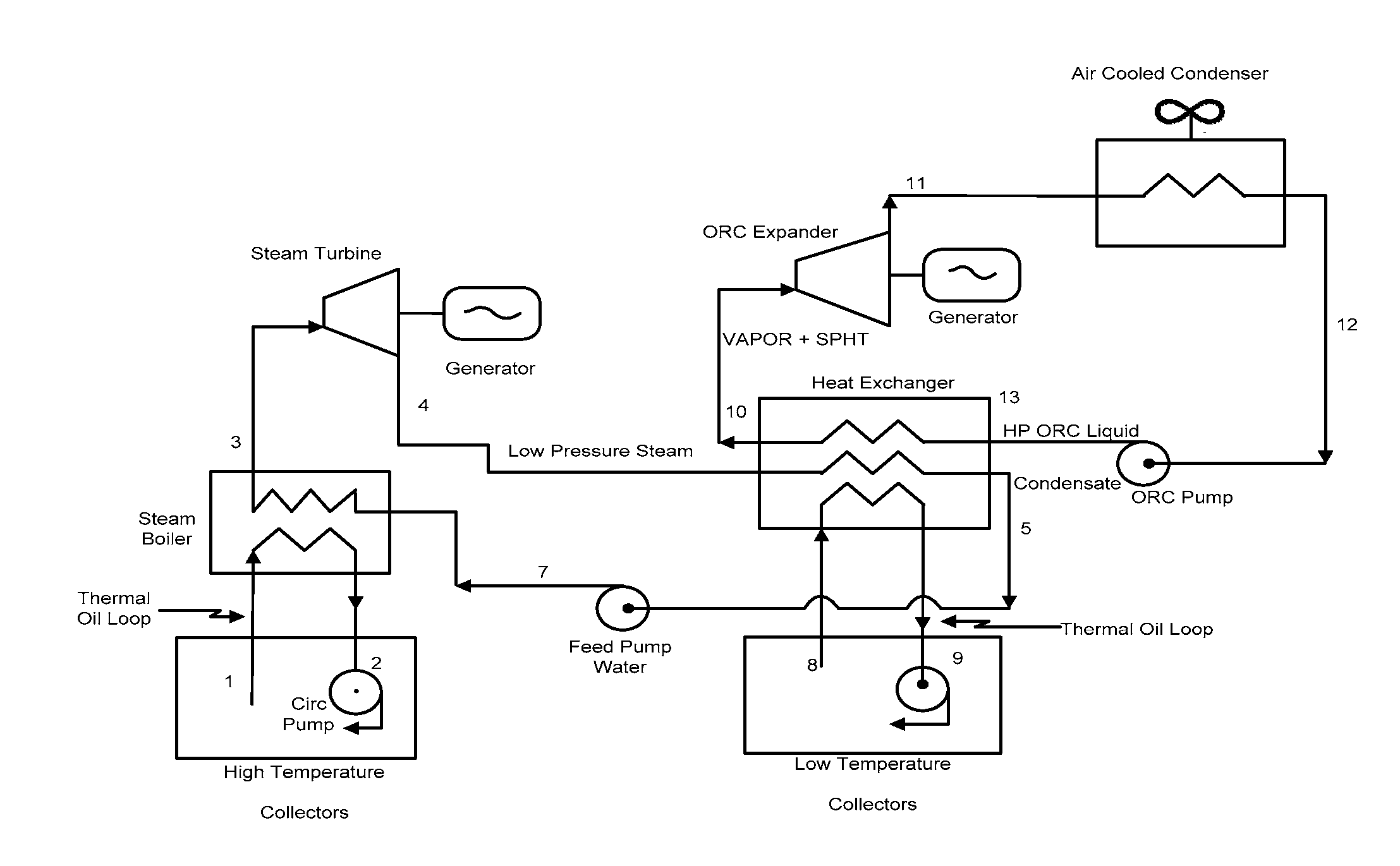
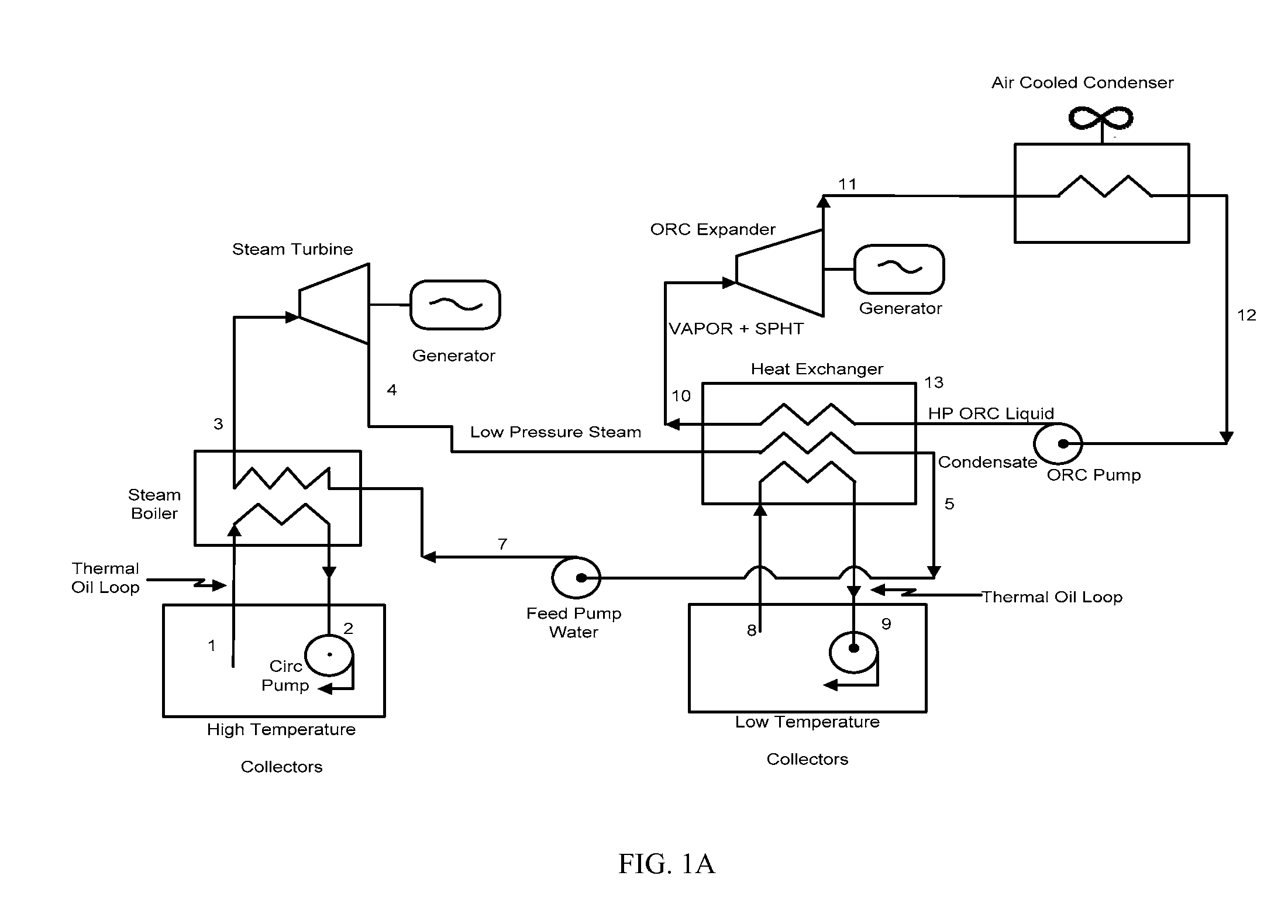
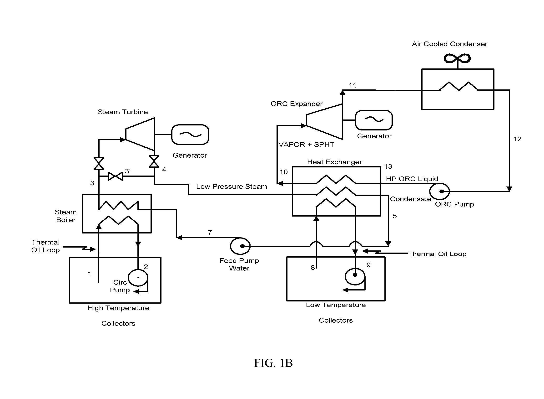
[0031]The invention provides thermal solar power generation using multiple working fluids in a Rankine cycle. Prior power plants and energy generation systems include solar collectors that provide heat at the same temperature. From a system thermodynamics consideration, the use of such uniform collectors is sub-optimal and more expensive than necessary. If the temperature of thermal fluid returning to the collector field is much lower (e.g., 300° F.) than the thermal fluid leaving the field, much of the input heat requi...


PUM


Abstract

A system to convert the heat collected by solar thermal collectors into electricity using a Rankine cycle generator with multiple working fluids and multiple temperature-level heat sources is disclosed.

Description

CROSS-REFERENCE[0001]This application claims the benefit of U.S. Provisional Application No. 61 / 090,097, filed Aug. 19, 2008, which application is incorporated herein by reference in its entirety.FIELD OF INVENTION[0002]The invention relates generally to the generation of electricity using solar collectors and an organic Rankine cycle. In particular, the invention relates to the generation of electricity from solar collectors using different temperature heat sources in a multiple-fluid Rankine cycle system.BACKGROUND OF THE INVENTION[0003]The generation of electric power (or electricity) using a Rankine cycle in conjunction with the heat produced in a solar collector system is in widespread use. The solar thermal collectors are typically of a trough, dish or central receiver (power tower) design. Of these, the parabolic, tracking trough-type collectors appear to be the most popular. Typically, these systems reflect the solar rays to a cylindrical pipe (receiver) located at the focal...

Claims


Application Information

Patent Timeline
Patent Type & Authority Applications(United States)
IPC IPC(8): F03G7/00F03G6/00
CPCF01K23/04F01K25/10Y02E10/46F22B1/006F03G6/067
Inventor LEIBOWITZ, HERMAN
Owner TAS ENERGY
Why Eureka
Try Eureka