Gas sensor

a technology of gas sensor and detection element, which is applied in the field of gas sensor, can solve the problems of thermal shock to the detection element and cracking, and achieve the effects of preventing cracking in the detection element, and preventing deterioration in detection accuracy

Inactive Publication Date: 2011-09-01
NGK SPARK PLUG CO LTD
View PDF11 Cites 32 Cited by
  • Summary
  • Abstract
  • Description
  • Claims
  • Application Information

AI Technical Summary

Benefits of technology

[0022]The gas sensor of an invention according to configuration 1 comprises the protector having the inner protector and the outer protector. Thus, even when, with clogging of the outer gas inlet taken into consideration, the outer gas inlet is relatively increased in size, water and soot adhere to the inner wall portion of the inner protector, whereby adhesion of water and soot to the detection element can be restrained. As a result, the generation of cracking in the detection element can be restrained, and a deterioration in detection accuracy can be restrained.
[0023]Further, preferably, the temperature of the inner protector is 280° C. or higher. By virtue of this, water adhering to the inner wall portion can be positively evaporated, and soot can be positively removed from the inner wall portion. As a result, water and soot which once adhere to the inner wall portion can be prevented from being again contained in the gas to be measured which is to be introduced toward the detection element through the inner gas inlet, whereby adhesion of water and soot to the detection element can be restrained.
[0024]Meanwhile, according to the present invention, in order for the inner protector to have a temperature of 280° C. or higher, the inner protector is configured to receive heat from the heater adapted to heat the detection portion. This eliminates the need to separately provide heating means for heating the inner protector, thereby simplifying configuration.
[0025]In this case, when the gas sensor is in use, the temperature of the inner protector is rendered higher than that of the outer protector. This makes the outer protector less likely to receive heat from the heater, whereby the inner protector can efficiently have a temperature of 280° C. or higher. Accordingly, water adhering to the inner wall portion can be evaporated, and soot adhering to the inner wall portion can be burned or removed from the inner wall portion. As a result, adhesion of water and soot to the detection element can be restrained.
[0026]Specifically, the inner protector (inner wall portion) and the detection portion are disposed with a gap existing therebetween and such that a clearance of 1.35 mm or less is provided between the detection portion and at least a portion of the inner wall portion. By virtue of this, the inner protector has a temperature of 280° C. or higher through reception of heat from the heater laminated on the detection element and becomes higher in temperature than the outer protector. When the inner protector (inner wall portion) and the detection portion are in contact with each other, heat of the heater is conducted excessively to the inner protector; consequently, additional heater power is required for maintaining the detection portion at a predetermined temperature. Meanwhile, when the clearance between the inner wall portion and the detection portion is in excess of 1.35 mm, the inner protector is less likely to receive heat from the heater, so that difficulty is encountered in increasing the temperature of the inner protector.
[0027]The expression “when the gas sensor is in use, the inner protector is higher in temperature than the outer protector” means the following: when the gas sensor installed in the intake passage is detecting a particular gas component contained in gas to be measured, a temperature at any point on the inner protector is higher than a temperature at any point on the outer protector; and at the normal temperature, the inner protector and the outer protector may have the same temperature.

Problems solved by technology

Thus, the detection element is subjected to thermal shock and may be cracked.

Method used


Image

  • Gas sensor
  • Gas sensor
  • Gas sensor

Examples


Embodiment Construction

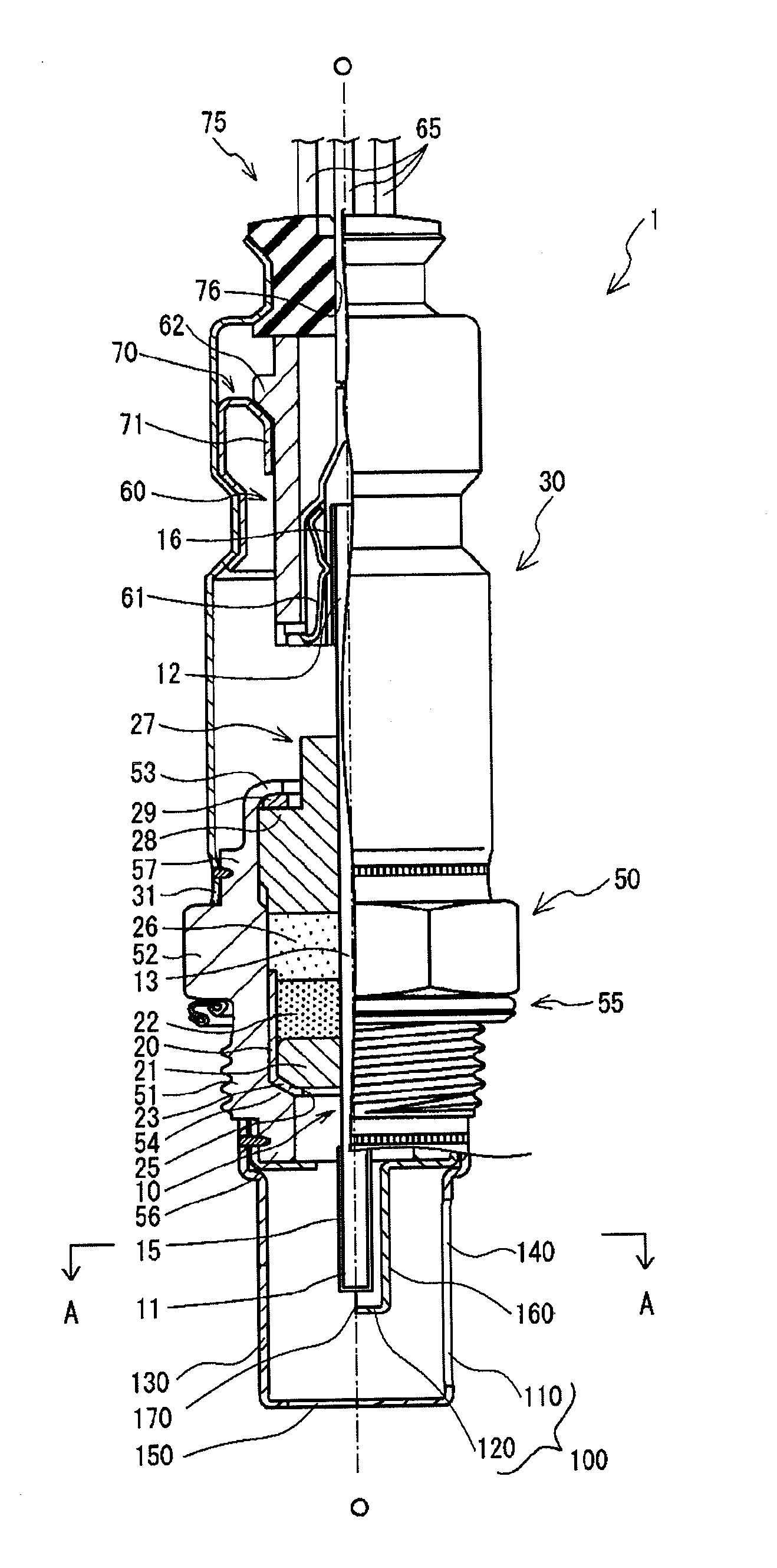
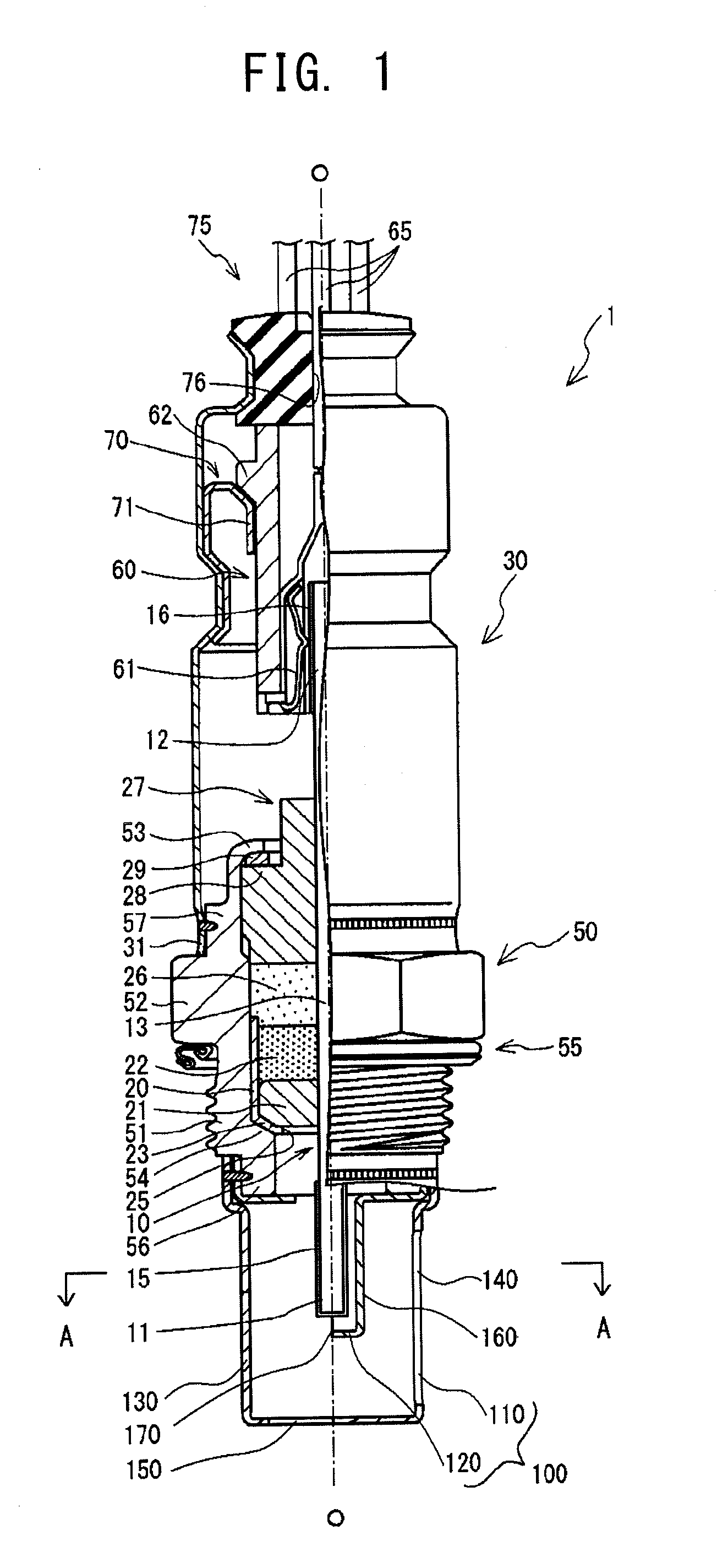
[0052]A gas sensor according to an embodiment of the present invention will next be described with reference to the drawings. First, the structure of a gas sensor 1 will be described, by way of example, with reference to FIG. 1. FIG. 1 is a partially sectional view of the gas sensor 1. In FIG. 1, the direction of an axis O (represented by a dash-dot line) of the gas sensor 1 coincides with the vertical direction. In the following description, a side toward a detection portion 11 of a detection element 10 held in the interior of the gas sensor 1 is referred to as a front side of the gas sensor 1, and a side toward a rear end portion 12 is referred to as a rear side of the gas sensor 1.

[0053]The gas sensor 1 shown in FIG. 1 is attached to an intake passage 2 (see FIG. 5) of an internal combustion engine. The detection portion 11 of the detection element 10 held in the interior of the gas sensor 1 is exposed to intake gas or intake recirculation gas which flows through the intake passa...


PUM


Abstract

A gas sensor (1) has an inner protector (120) and an outer protector (110); the inner protector (120) has an inner wall portion (160) having an inner gas inlet (170) for introducing gas to be measured into the interior of the inner protector (120); the outer protector (110) has an outer wall portion (130) having an outer gas inlet (140) for introducing the gas to be measured into the interior of the outer protector (110); a clearance of 1.35 mm or less is provided between the detection portion (11) and at least a portion of the inner wall portion (160); and when the gas sensor (1) is in use, the inner protector (120) is higher in temperature than the outer protector (110).

Description

TECHNICAL FIELD[0001]The present invention relates to a gas sensor to be disposed in an intake passage, such as an intake gas passage through which intake gas supplied from the outside flows to an internal combustion engine, or an intake recirculation gas passage through which intake recirculation gas (recirculated exhaust gas) flows for reducing contaminant emission from the internal combustion engine.BACKGROUND ART[0002]Conventionally, in order to detect the oxygen concentration of intake gas (the air) supplied from the outside to an internal combustion engine, the following technique is employed: a gas sensor is disposed in an intake gas passage of the internal combustion engine, and the detected oxygen concentration is used in operation control of the internal combustion engine, thereby improving accuracy in air-fuel-ratio control of the internal combustion engine (refer to, for example, Patent Document 1).[0003]Also, in recent years, for the purpose of reducing nitrogen oxides ...

Claims


Application Information

Patent Timeline
Patent Type & Authority Applications(United States)
IPC IPC(8): G01M15/10
CPCG01N27/4077
Inventor OTSUBO, MASANORIYOSHIKAWA, TAKAYATAJIMA, TOMOHIROTSUZUKI, MASAO
Owner NGK SPARK PLUG CO LTD
Why Eureka
Try Eureka