Method and system for cooling apparatus racks

a technology for cooling apparatus and racks, applied in the field of cooling, can solve the problems of increasing the cost of data center floor space, not being economical to space computer units, and producing heat typically by computer units and electrical cables, so as to reduce the overall cost of data center cooling, increase capacity, and increase heat load

Inactive Publication Date: 2011-09-01
TELIASONERA
View PDF15 Cites 11 Cited by
  • Summary
  • Abstract
  • Description
  • Claims
  • Application Information

AI Technical Summary

Benefits of technology

[0018]In one embodiment of the invention the space surrounding a device mounted to the rack inside the first or second apparatus rack is hindered from air flow, thereby forcing the laminar airflow to pass through the device. This enhances the cooling effect. The air flow may be hindered to only part of the rack, depending on the cooling requirements of an individual device mounted to the apparatus rack.
[0026]The invention relates also to a system for cooling a device mounted to an apparatus rack, comprising a first cooling unit, a first apparatus rack and at least one device mounted to said apparatus rack. According to the invention said first cooling unit is arranged in parallel with said first apparatus rack placed at a distance allowing maintenance work in the area between the first cooling unit and the first apparatus rack, said first cooling unit being configured to produce a substantially horizontal laminar cooled airflow, said airflow being evenly distributed over the side of first apparatus rack facing the first cooling unit. Cooling units produce the effect of a cool wall, where the horizontal laminar airflow appears to cover majority of the apparatus rack side facing the cooling unit. Arranging such cooling units to a row formation further enhances this cool wall effect.
[0029]The benefits of the invention are related to the improved cooling of apparatus racks and reduction in power consumption. The horizontal, uniform airflow reduces the occurrence of hot spots inside a densely built apparatus rack.
[0031]The effect of increased capacity enables the system to manage much higher heat loads with smaller coolant fluid temperature differences between the outlet and inlet of primary cooling circuit. For example to obtain a constant 22 degrees Celsius in the apparatus rack, the inlet fluid may be just 20 degrees Celsius. This enables the coolant fluid to be water or any other environmentally friendly material. Additionally the secondary cooling circuit may be cooled by outdoor air, chiller, or naturally flowing water from a river, lake or sea thereby increasingly reducing the overall costs of the data center cooling.
[0032]As the data center is well organized between two rows of cooling units, it is clear for the installer to know which aisle is the cool aisle and which aisle is the hot aisle. This reduces the risk of installing a device to a rack in a manner where its fan operates against the airflow.
[0033]Refurbishing existing data centers according to the present invention is easy. Cooling units can be positioned above the raised floor configuration or onto a normal solid floor. Using water or similar easily available cooling fluid leads to easy assembly.

Problems solved by technology

A problem of apparatus racks is the production of heat typically by computer units and electrical cables.
In data centers it is not economical to space the computer units with a sufficient distance from one another to get rid of active cooling.
This increases the cost of a data center's floor space significantly.
Abnormal hot spots in a rack mounted device may lead to breakage of the device or to reduced service level.
The problem in existing cooling system such as illustrated in FIG. 1 is the power consumption required to keep the racks at a sufficiently low temperature.
This creates high requirements for the heat dissipation, for example, through secondary circuit and limits the free-cooling period severely.
The problem is exacerbated by a more tight packing of circuit boards in apparatus racks typically in modern blade servers.
Another problem of an arrangement as illustrated in FIG. 1 is, that it is possible to mount a single device into the rack in a reverse manner, i.e. the air flow is directed opposite to the general hot aisle-cold aisle configuration.

Method used


Image

  • Method and system for cooling apparatus racks
  • Method and system for cooling apparatus racks
  • Method and system for cooling apparatus racks

Examples


Embodiment Construction

[0038]Reference will now be made in detail to the embodiments of the present invention, examples of which are illustrated in the accompanying drawings.

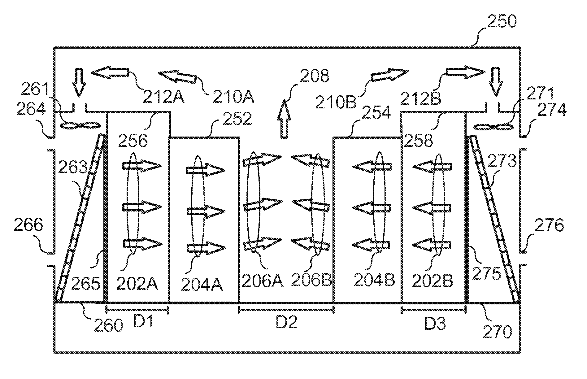
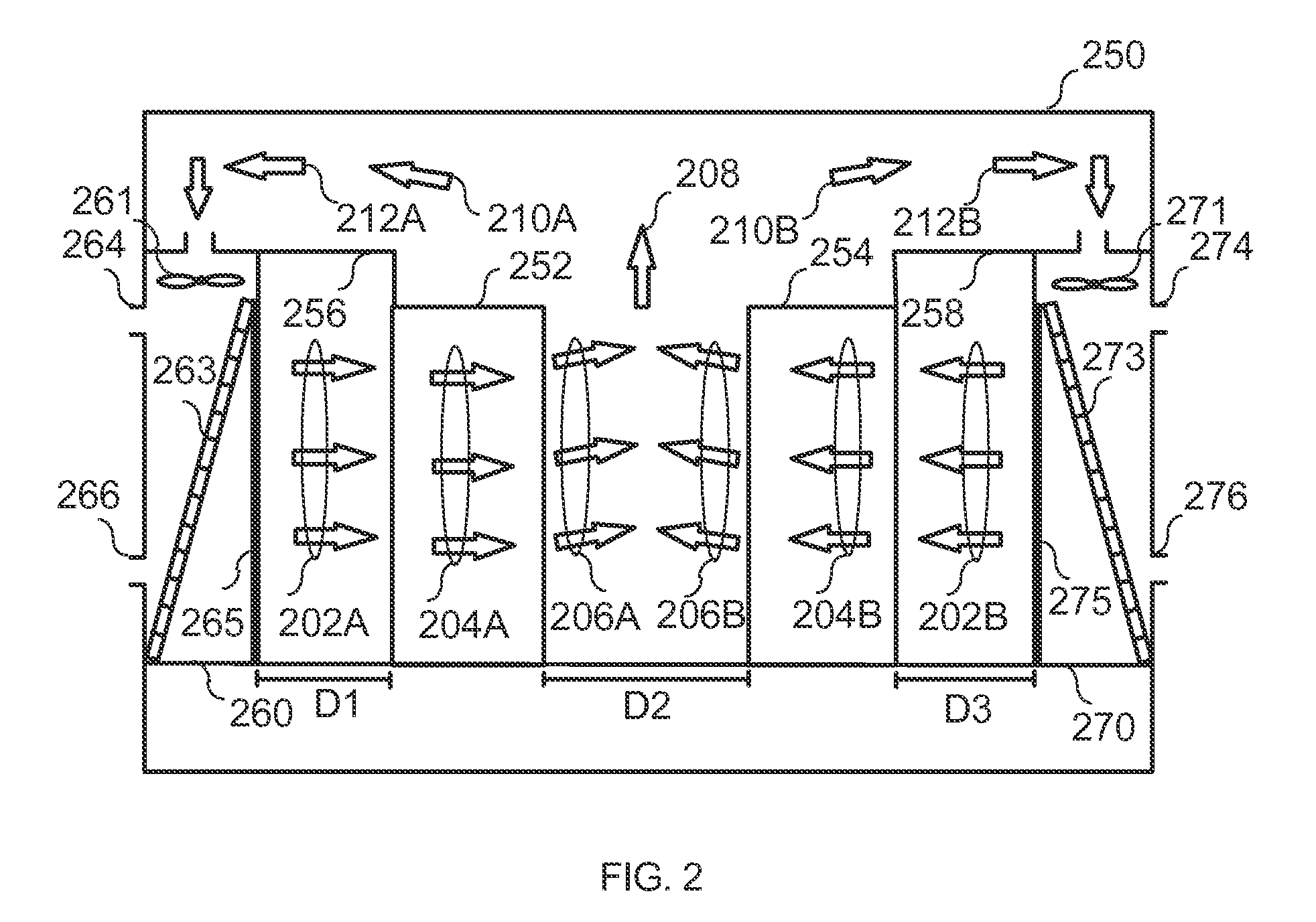
[0039]FIG. 2 illustrates a system for cooling apparatus racks in one embodiment of the invention. The system comprises a first cooling unit 260 and a second cooling unit 270. The cooling units may be similar as common air conditioning units or CRAC units. An example of a preferred embodiment for a cooling unit suitable for the invention is disclosed in EP958720B1.

[0040]The cooling unit may also have a primary cooling circuit with internal cooling battery. The primary cooling circuit may be coupled to a secondary cooling circuit that dissipates the heat load by free cooling, chillers or to preferred location outside the data centre, such as to water from a river or to outdoor air. The secondary cooling circuit may be any system known to a skilled man in the art.

[0041]Cooling units 260 and 270 have respective primary cooling circuit inl...


PUM


Abstract

The invention relates to a system and method that comprises at least two parallel apparatus racks and at least two cooling units. The cooling units are configured to produce horizontal cooled airflows toward outer sides of the at least two apparatus rack. The cooling units comprise an upper side inlet for airflow to be cooled. The system and method achieve a more effective cooling of apparatus racks.

Description

BACKGROUND OF THE INVENTION[0001]1. Field of the Invention[0002]The invention relates to cooling. Particularly, the invention relates to a method and a system for cooling apparatus racks, especially with high heat loads.[0003]2. Description of the Related Art[0004]Apparatus racks are used to house interrelated electronic or otherwise functional devices with a similar or related heat dissipation function. The electronic devices may represent stripped down versions of devices such as a computers that might otherwise be provided with a separate housing or cover. The devices are usually connected with an electrical connection. The racks are usually provided with shared power units and in some cases shared fan trays. The electronic devices are typically computer units comprising microprocessors, memory circuits and hard disc units. Also other devices producing heat loads may be installed into an apparatus rack. A rack may typically comprise a conventional horizontally mounted server, ver...

Claims


Application Information

Patent Timeline
Patent Type & Authority Applications(United States)
IPC IPC(8): F28D15/00
CPCH05K7/20745
Inventor ENLUND, SVANTE
Owner TELIASONERA
Why Eureka
Try Eureka