
Display device and e-book reader provided therewith

a display device and e-book reader technology, applied in the direction of instruments, computing, electric digital data processing, etc., can solve the problems of lower visible efficiency in text reading, sentence comprehension, image recognition, and difficulty in detecting text, so as to prevent the effect of lower visible efficiency in changing display and deterioration of display quality

Inactive Publication Date: 2011-09-01
SEMICON ENERGY LAB CO LTD
View PDF101 Cites 23 Cited by
  • Summary
  • Abstract
  • Description
  • Claims
  • Application Information

AI Technical Summary

Benefits of technology

[0006]According to Patent Document 1, power consumption can be reduced by lowering the refresh rate in displaying a still image. However, in a structure in Patent Document 1, because a transistor used for a pixel is formed using amorphous silicon, it is possible that voltage applied to a liquid crystal element which is a display element is decreased due to the off-state current of the transistor. In addition, in Patent Document 1, because time needed for rewriting an image is short, an image is momentarily updated to a newly written image when different images are switched by supplying different image signals between a period and the next period to perform display; which is different from a paper medium.
[0007]An object of an embodiment of the present invention is to provide a display device in which deterioration in display quality due to a change in voltage applied to a display element is reduced and a lower visible efficiency in changing display is prevented
[0013]An embodiment of the present invention can provide a display device in which deterioration in display quality due to a change in voltage applied to a display element is reduced and a lower visible efficiency in changing display is prevented.

Problems solved by technology

Such a difference in the way they are handled causes the display media a problem such as a lower visible efficiency in text reading, sentence comprehension, or image recognition than the paper media.

Method used


Image

  • Display device and e-book reader provided therewith
  • Display device and e-book reader provided therewith
  • Display device and e-book reader provided therewith

Examples


embodiment 1

(Embodiment 1)

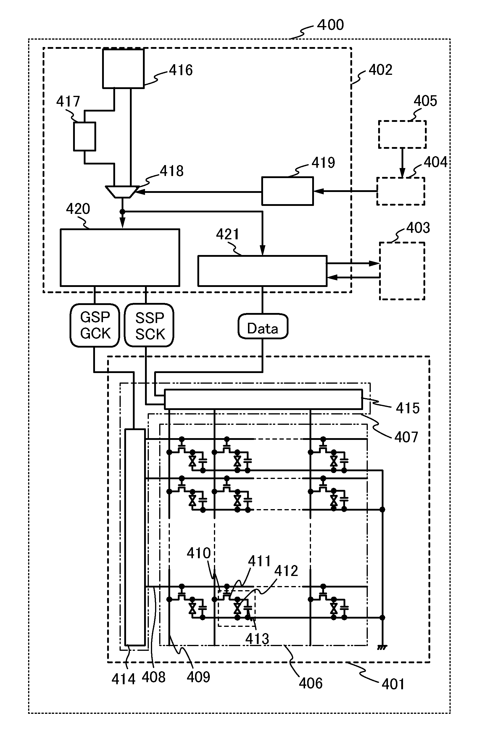
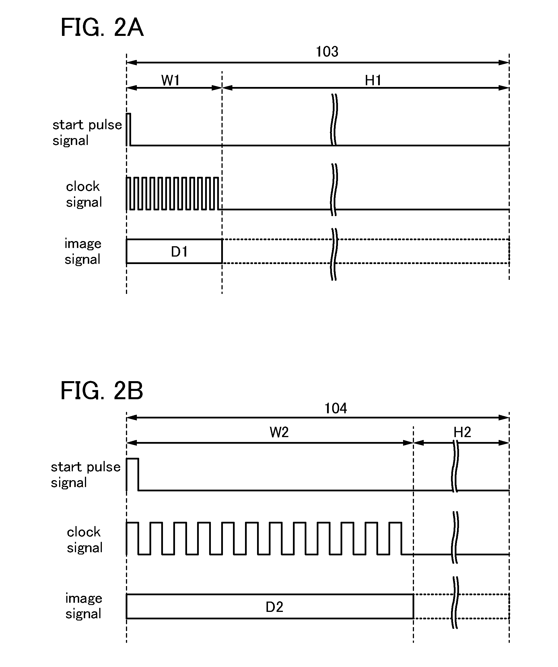
[0028]In this embodiment, operation of a display device will be described with reference to a schematic view, a timing chart, a block diagram, a flowchart, or the like.

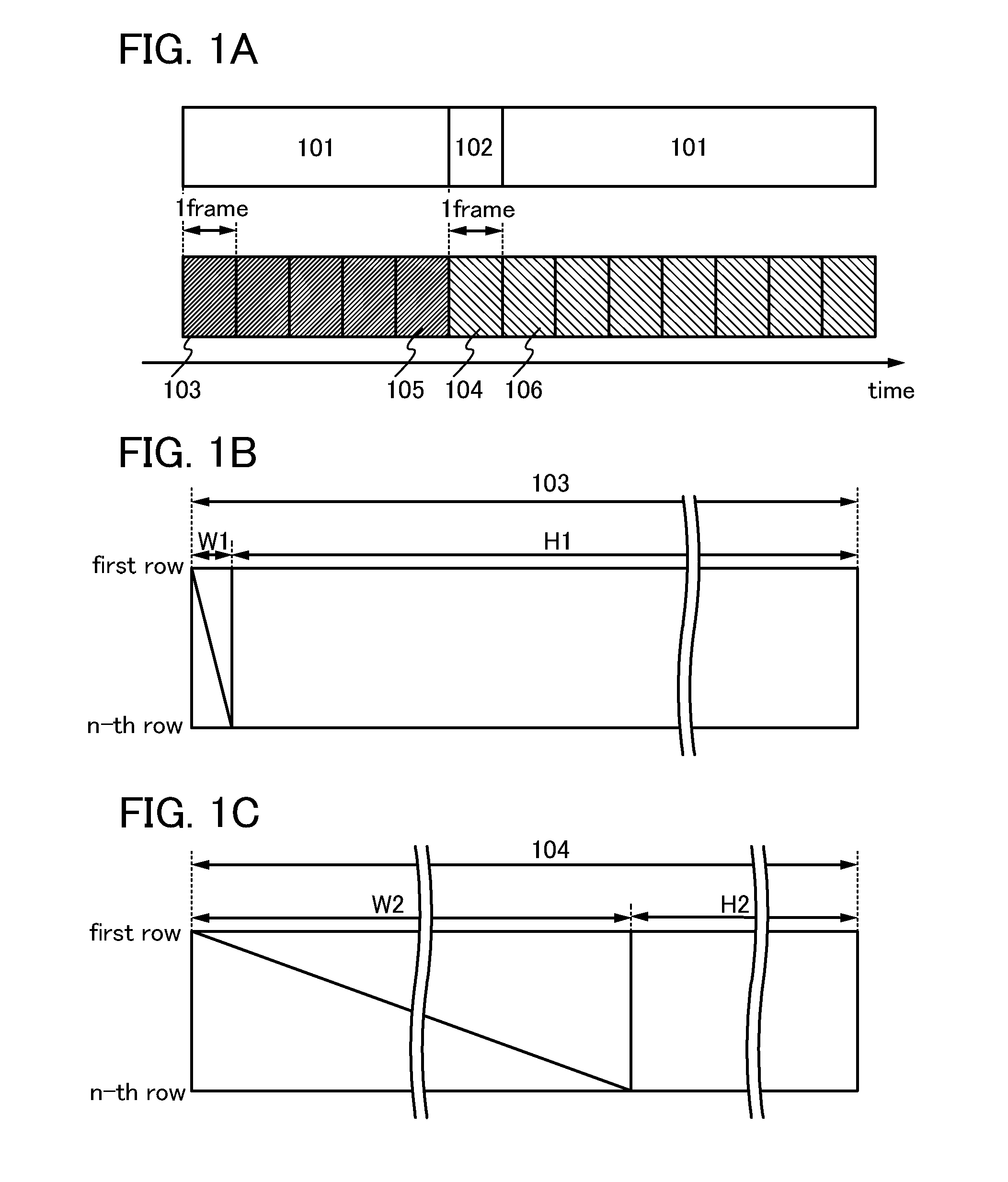
[0029]First, FIGS. 1A to 1C illustrate schematic views of a driving method of the display device. In this embodiment, a liquid crystal display device is described as an example of the display device.

[0030]Operation of the liquid crystal display device in this embodiment is roughly divided into an operation in a first still image display period 101 (also referred to as a first period) and an operation in a second still image display period 102 (also referred to as a second period) as illustrated in FIG. 1A.

[0031]The first still image display period 101 is a period during which one still image is displayed for sequential frame periods in which one image is displayed. An image signal (hereinafter, a first image signal) is written at a uniform refresh rate in the first still image display period 101. Accordi...

embodiment 2

(Embodiment 2)

[0070]In this embodiment, an example of a transistor which can be applied to a display device disclosed in this specification will be described.

[0071]FIGS. 7A to 7D each illustrate an example of a cross-sectional structure of a transistor.

[0072]A transistor 1210 illustrated in FIG. 7A is a kind of bottom-gate structure transistor and is also called an inverted staggered transistor.

[0073]The transistor 1210 includes, over a substrate 1200 having an insulating surface, a gate electrode layer 1201, a gate insulating layer 1202, a semiconductor layer 1203, a source electrode layer 1205a, and a drain electrode layer 1205b. An insulating layer 1207 is provided to cover the transistor 1210 and be stacked over the semiconductor layer 1203. A protective insulating layer 1209 is provided over the insulating layer 1207.

[0074]A transistor 1220 illustrated in FIG. 7B has a kind of bottom-gate structure called a channel-protective type (channel-stop type) and is also referred to as ...

embodiment 3

(Embodiment 3)

[0105]In this embodiment, an appearance and a cross section of a liquid crystal display device is illustrated and a structure thereof will be described. Specifically, when transistors are manufactured and used for a pixel portion and a driver circuit, a liquid crystal display device having a display function can be manufactured. Further, part of or the entire driver circuit can be formed over a substrate where a pixel portion is formed, using a transistor; thus, a system-on-panel can be obtained.

[0106]Note that the liquid crystal display device includes any of the following modules in its category: a module provided with a connector, for example, a flexible printed circuit (FPC), a tape automated bonding (TAB) tape, or a tape carrier package (TCP); a module provided with a printed wiring board at the end of a TAB tape or a TCP; and a module where an integrated circuit (IC) is directly mounted on a display element by a chip-on-glass (COG) method.

[0107]The appearance and...


PUM


Abstract

An object is to provide a display device in which deterioration in display quality due to a change in voltage applied is reduced and a lower visible efficiency in changing display is prevented. The display device has a display controller configured to make the display portion perform display by switching a first still image display period including a writing period in which a first image signal is written and a holding period in which the first image signal is held, and a second still image display period including a writing period in which a second image signal is written and a holding period in which the second image signal is held. The display controller is configured to make a length of the writing period of the first still image display period and a length of the writing period of the second still image display period different from each other.

Description

TECHNICAL FIELD[0001]The present invention relates to a driving method of a display device. Further, the present invention relates to a display device. Furthermore, the present invention relates to an e-book reader provided with a display device.BACKGROUND ART[0002]In recent years, as a digitization technology has been developed, image data and text data of a newspaper, a magazine, and the like can be provided as electronic data. The contents of such a kind of electronic data are generally read by being displayed on a display device included in a television, a personal computer, a portable electronic terminal, or the like.[0003]Display media such as a liquid crystal display device are very different form paper media such as a newspaper and a magazine. One of features of display media is that pages are switched on a screen of a display device, which is very different from the way paper media usually are handled. Such a difference in the way they are handled causes the display media a...

Claims


Application Information

Patent Timeline
IPC IPC(8): G09G5/00
CPCG09G2340/0435G09G3/3648G09G2380/14
Inventor YAMAZAKI, SHUNPEIKOYAMA, JUN
Owner SEMICON ENERGY LAB CO LTD
Learn More