

Combined Radiation Therapy and Magnetic Resonance Unit
- Summary
- Abstract
- Description
- Claims
- Application Information
AI Technical Summary
Benefits of technology
Problems solved by technology
Method used
Image

Examples
Embodiment Construction
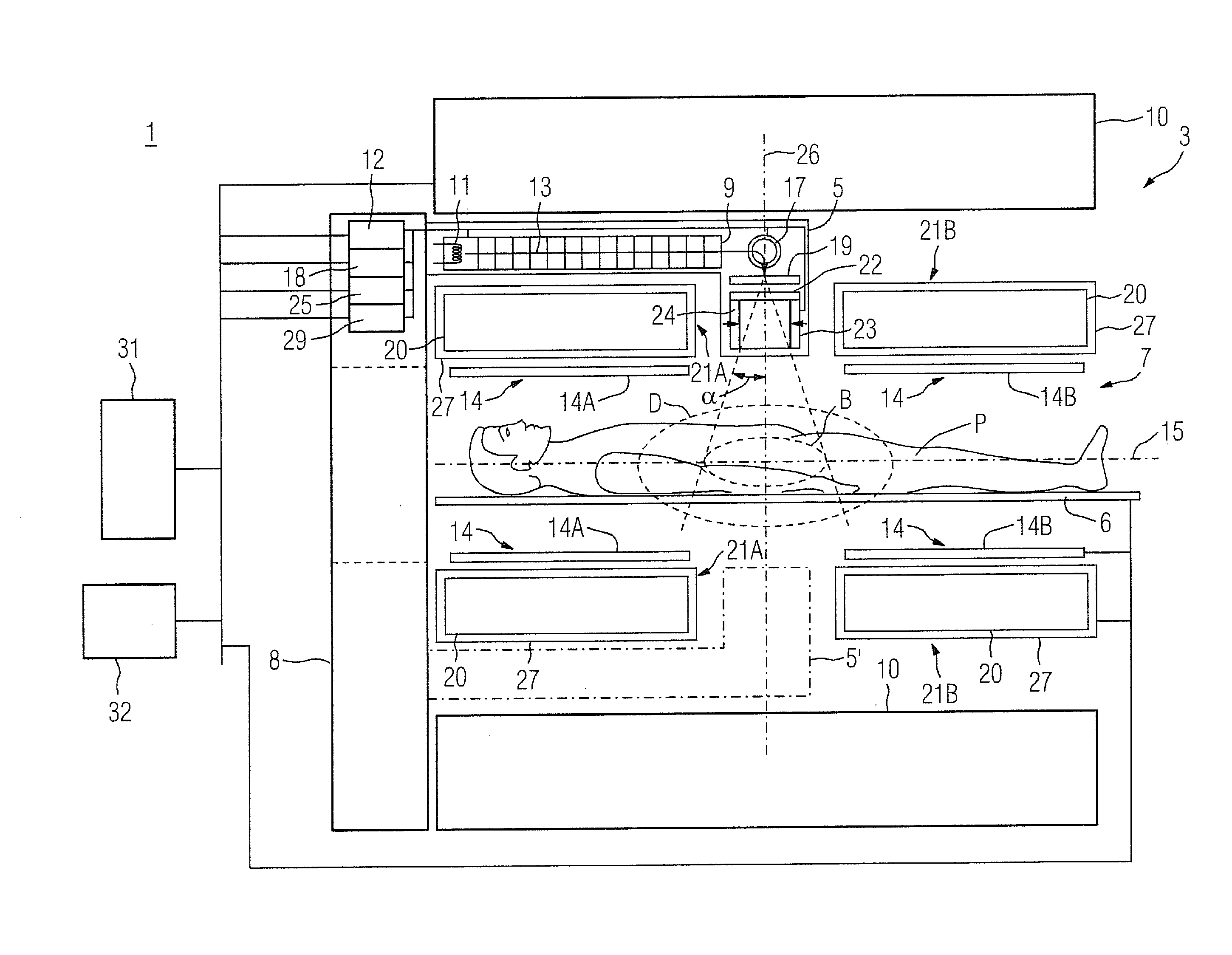
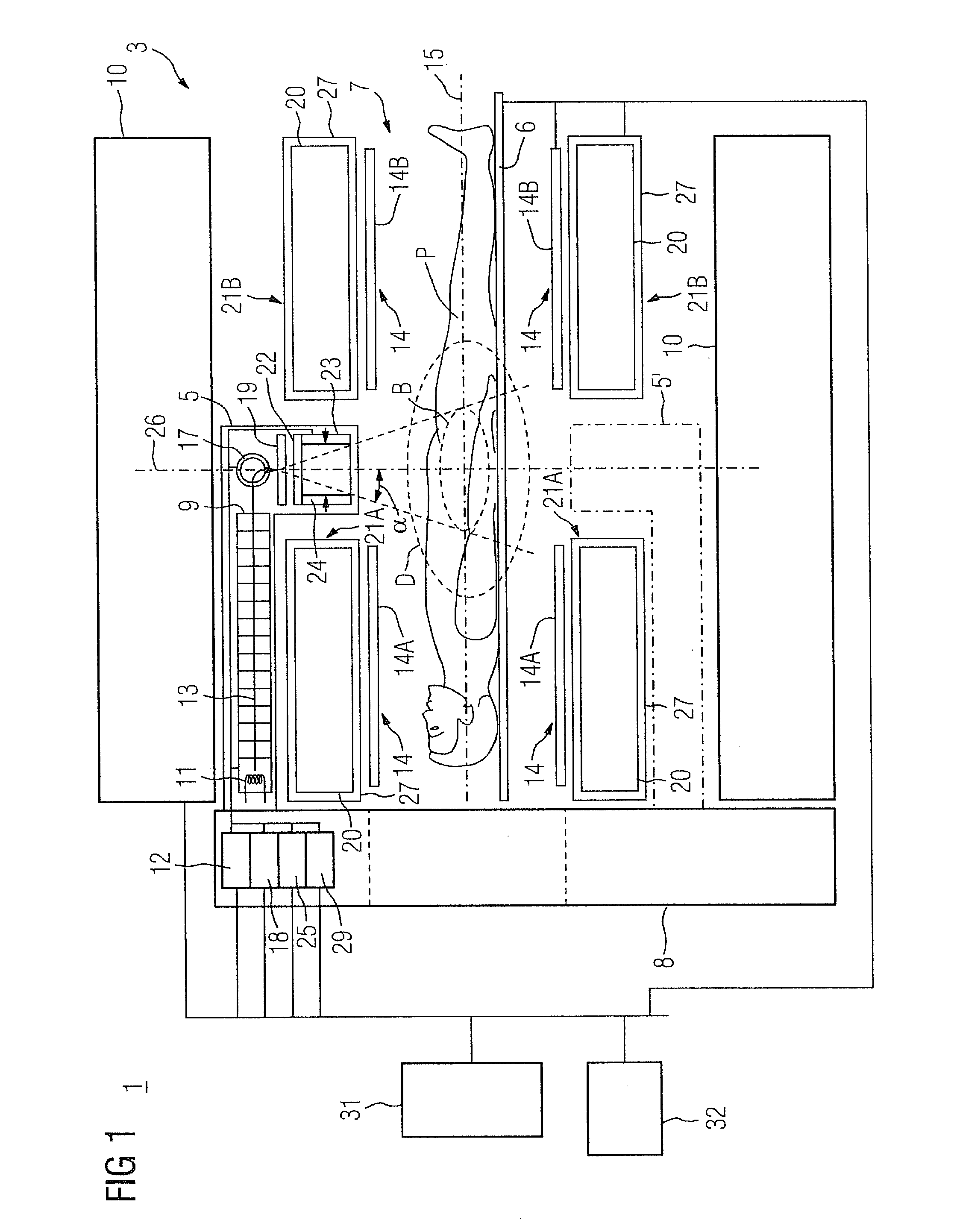
[0034]FIG. 1 shows a schematic representation (not to scale) of a combined radiation therapy and magnetic resonance unit 1 with a magnetic resonance diagnosis part 3 and a radiation therapy part 5. The magnetic resonance diagnosis part 3 comprises a main magnet 10, a gradient coil system comprising two in this case symmetrical partial gradient coils 21A,21B, high-frequency coils 14, for example two parts of a body coil 14A,14B, and a patient bed 6. All these components of the magnetic resonance part are connected to a control unit 31 and an operating and display console 32.
[0035]In the example presented, both the main magnet 10 and the partial gradient coils 21A,21B are essentially shaped like a hollow cylinder and arranged coaxially around the horizontal axis 15. The inner shell of the main magnet 10 limits in radial direction (facing away vertically from the axis 15) a cylinder-shaped interior 7, in which the radiation therapy part 5, the gradient system, high-frequency coils 14 a...
PUM
 Abstract
Description
Claims
Application Information