Parametric product configuration system

a product configuration and parametric technology, applied in the direction of configuration cad, knowledge representation, instruments, etc., can solve the problems of not being able to directly generate manufacturing drawings, accurate and immediate costing information, and not being able to dynamically program the configuration functionality, etc., and not being able to provide generic product configuration capability or accurate and immediate costing. , the system is not designed to achieve the effect of providing accurate and immediate costing, and not allowing for dynamic programming of the configuration functionality

Inactive Publication Date: 2011-09-01
GENEXIS DESIGN
View PDF10 Cites 59 Cited by
  • Summary
  • Abstract
  • Description
  • Claims
  • Application Information

AI Technical Summary

Benefits of technology

[0012]The sketcher module and dynamic assembly logic module may be imp...

Problems solved by technology

Such design systems are typically built around the type of product they are intended to configure, and therefore do not allow for dynamic programming of the configuration functionality, or for new products to be incorporated quickly and easily.
Furthermore they have limited or no ability to directly generate bills of materials, manufacturing drawings and accurate and immediate costing information, and if such a function is available, its logic is typically hard-coded to the configuration product.
Commercially available computer-aided design (CAD) programs, such as AutoCAD and engineering computer-aided design (EGAD) programs, such as Pro/ENGINEER, SolidWorks and CATIA, can be used to generate bills of materials and manufacturing drawings, which is their primary purpose; however such systems are not designed to provide generic product configuration capability, or accurate and immediate costing.
CAD/ECAD programs can be used to build systems for configuring products, however such applications will typically not allow dynamic changes of configuration logic or easy modifications to the configuration architecture without cumbersome reprogramming of the logic.
Such configuration logic creations and modifications are time consuming, and require the involvement of highly skilled and highly paid CAD operators and programmers.
In CAD/ECAD based product configuration applications, there are inherent time delays in the processing of each configuration request du...

Method used


Image

  • Parametric product configuration system
  • Parametric product configuration system
  • Parametric product configuration system

Examples


Embodiment Construction

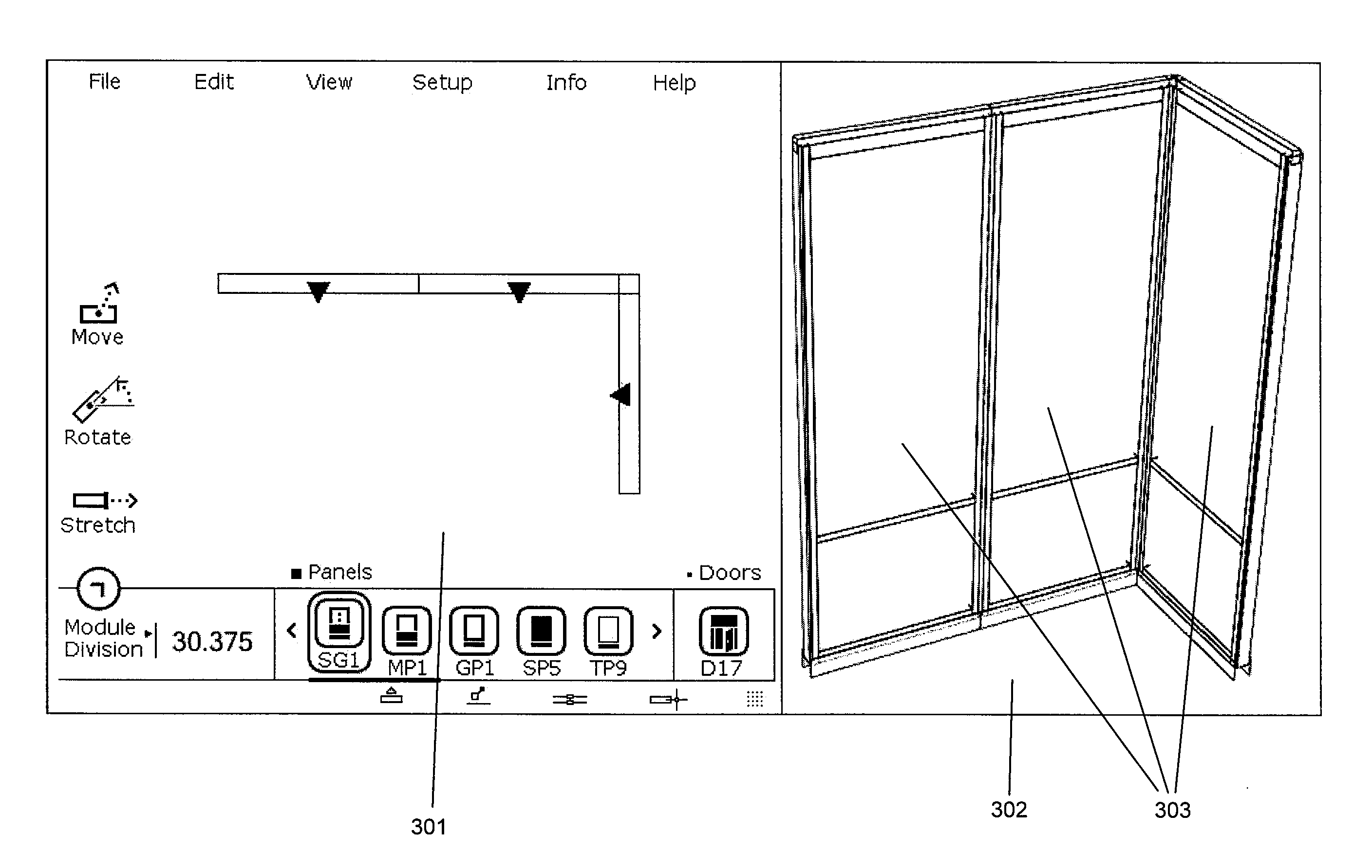
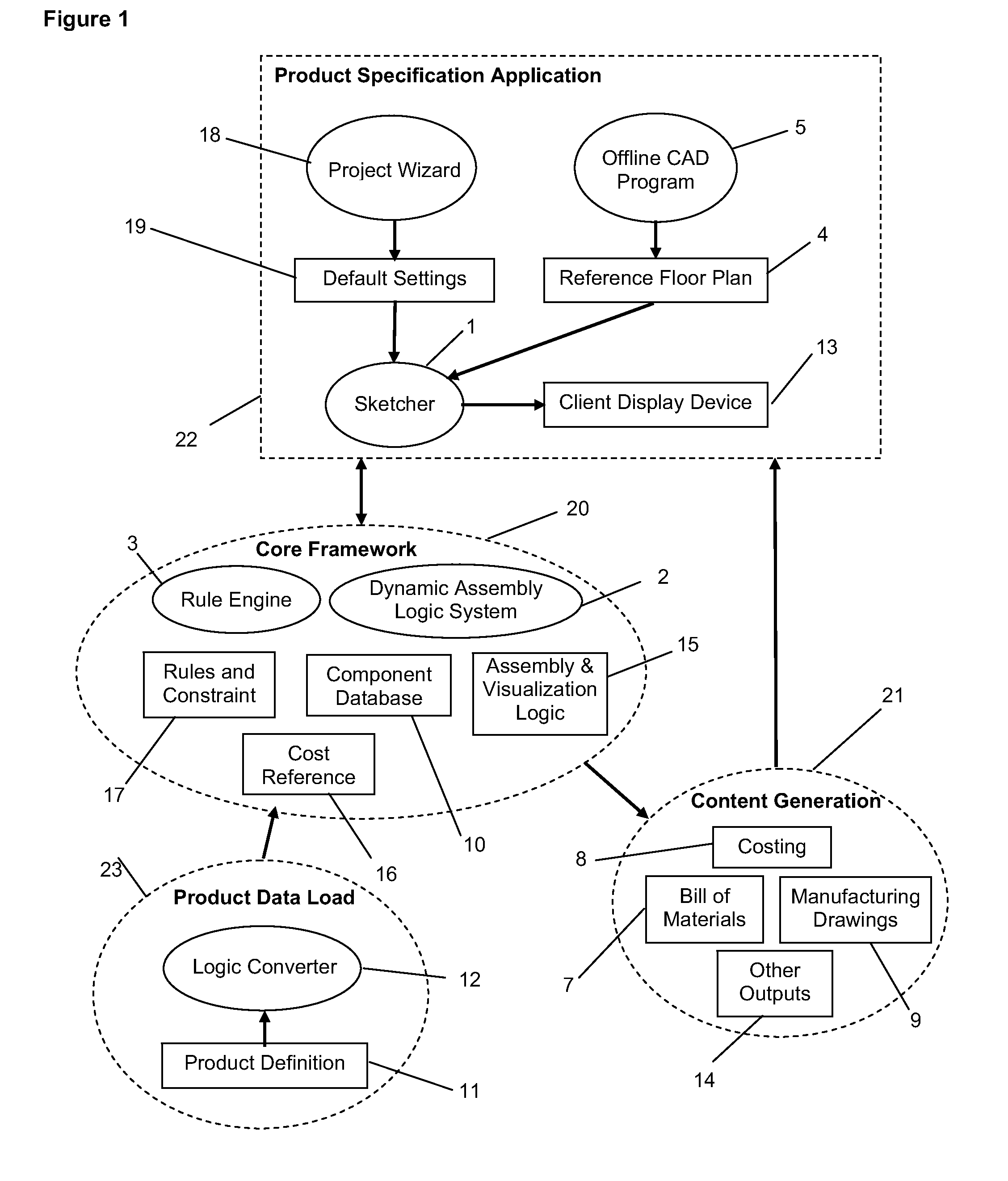
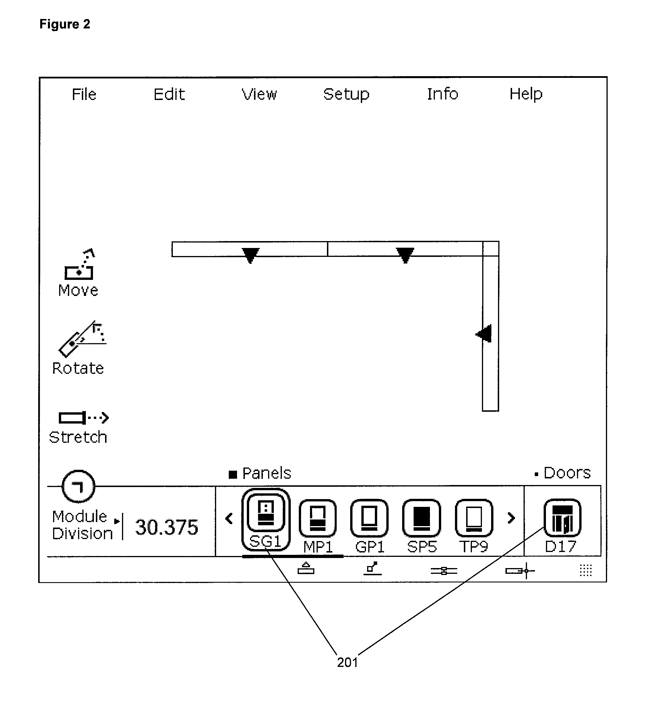
[0028]In a preferred embodiment depicted in FIG. 1, the system includes the following main components: a Product Specification Application 22, the Core Framework 20, the Product Data Load 23, and Content Generation 21. The Product Specification Application 22 is a custom application (such as a web site, rich internet application, or desktop application, that can interface with the Core Framework 20) designed to meet the needs of the particular type of product being configured. The Core Framework 20 contains the Product Definition Implementations, the validation provided by the Rule Engine 3 (also referred to as the rule engine module), and the content generation provided by the Dynamic Assembly Logic System 2 (also referred to as the dynamic assembly logic module). The Product Data Load 23 refers to the processes and methods in which users would typically transfer the knowledge and materials in the Product Definition 11 into the various forms to create the internal Product Definitio...


PUM


Abstract

A generic, integrated, parametric, automated product configuration system for parametric configuration of products such as offices on a building space plan. The system can produce bills of materials, costings and manufacturing drawings in real-time at the request of a user as the user specifies and configures the product components and parameters values. The system provides for real time three-dimensional visualization and editing of the product as it is configured. It also includes a rule engine for validating the product and automatically incorporating missing necessary components in a configuration in real-time as the user configures a product.

Description

FIELD OF THE INVENTION[0001]The invention relates to computerized parametric configuration systems and more particularly to a software application for designing configurations of configurable products.BACKGROUND OF THE INVENTION[0002]Many systems have been developed to provide design and modeling functions for assembling components into a product and customizing the product to a user's specifications. For example, they may allow users to design rooms, and place objects, such as furniture into those rooms. These systems employ custom software running on a user's computer, either in a standalone mode, or as a client that interacts with a server.[0003]Such design systems are typically built around the type of product they are intended to configure, and therefore do not allow for dynamic programming of the configuration functionality, or for new products to be incorporated quickly and easily. Furthermore they have limited or no ability to directly generate bills of materials, manufactur...

Claims


Application Information

Patent Timeline
IPC IPC(8): G06F17/50G06N5/02
CPCG06F2217/02G06F17/5004G06F2111/20G06F30/13
Inventor ZILA, VLADIMIRZILA, ZUZANASINCLAIR, CHRISTOPHER ADAMMANUEL, JASON JOSEPH
Owner GENEXIS DESIGN
Why Eureka
Try Eureka