
Signal Detection Device, Signal Detection Method, and Method of Manufacturing Signal Detection Device

a signal detection and signal technology, applied in measurement devices, instruments, electrical measurements, etc., can solve the problems of inability to employ discrete wavelet transformation, difficult and substantial computational complexity, and achieve the effect of signal detection in real time and substantial computational complexity

Inactive Publication Date: 2011-09-01
TOYOHASHI UNIVERSITY OF TECHNOLOGY
View PDF4 Cites 4 Cited by
  • Summary
  • Abstract
  • Description
  • Claims
  • Application Information

AI Technical Summary

Benefits of technology

[0035]An advantageous feature of current object signal detection methods based on wavelet instantaneous correlation WIC that rely on continuous wavelet transformation is that the generation time and the strength of

Problems solved by technology

However, the computational complexity involved is substantial, since continuous wavelet transformation is employed, and hence, signal detection in real time is difficult.
An RMW constructed on the basis of actually measured object signals does not satisfy the bi-orthogonality condition, and hence cannot be employed in discrete wavelet transformation.
However, as in the case of lifting schemes, the MW that is used must satisfy the bi-orthogonality condition, and thus only a limited number of MWs can be used.
In particular, an RMW constructed on the basis of actually measured object signals does not satisfy the bi-orthogonality condition, and hence cannot be employed in discrete wavelet transformation.

Method used


Image

  • Signal Detection Device, Signal Detection Method, and Method of Manufacturing Signal Detection Device
  • Signal Detection Device, Signal Detection Method, and Method of Manufacturing Signal Detection Device
  • Signal Detection Device, Signal Detection Method, and Method of Manufacturing Signal Detection Device

Examples


Embodiment Construction

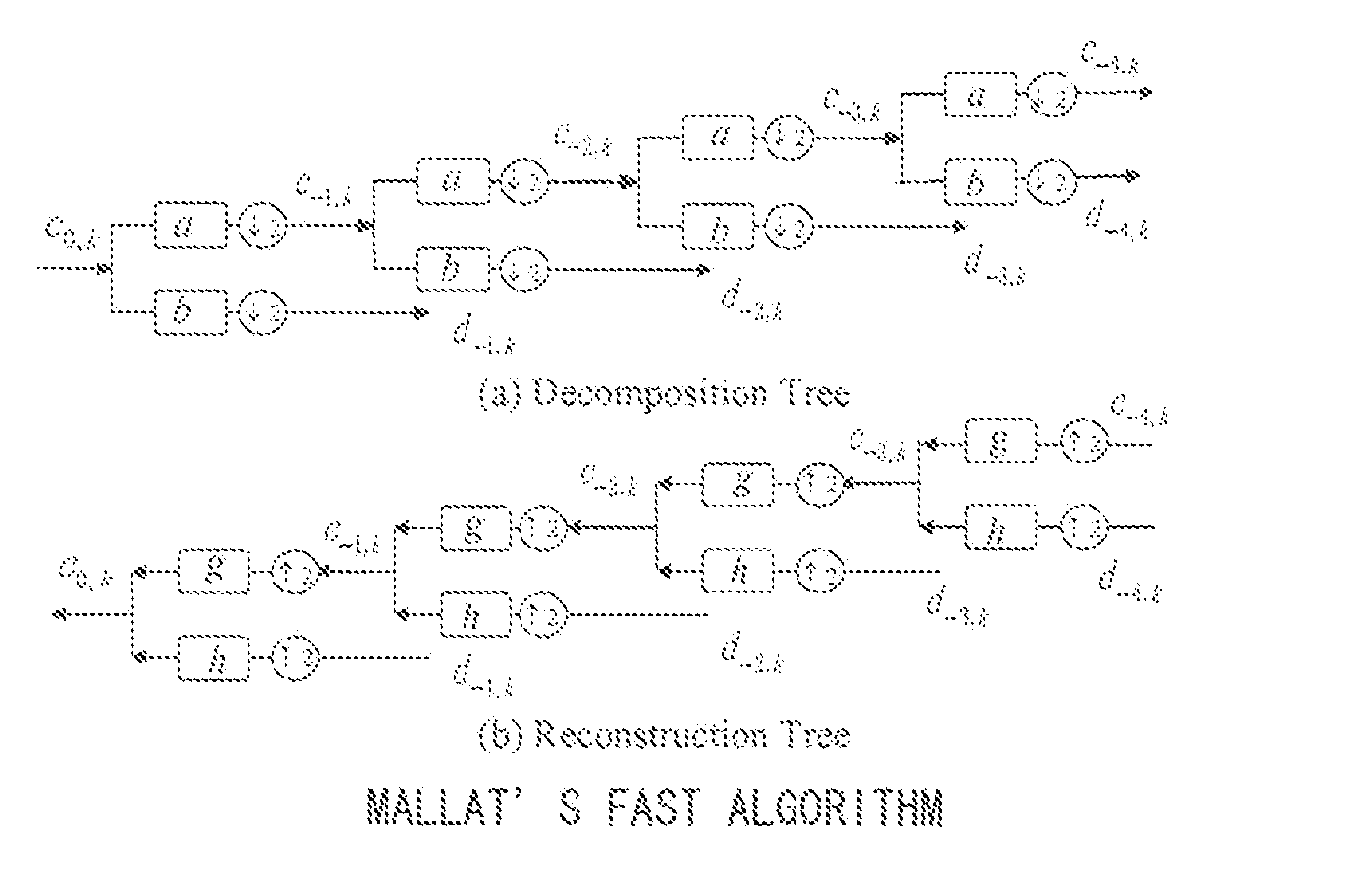
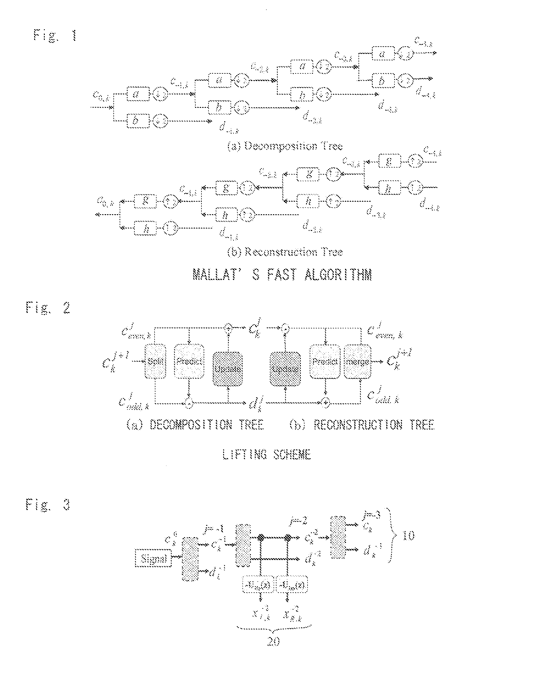
[0058]Lifting scheme structures and multiresolution analysis are known schemes for discrete wavelet transformation, but the former scheme is preferably used, from the viewpoint of enhancing computational speed.

[0059]A decomposition algorithm in a lifting scheme structure is illustrated in FIG. 2. As indicated by the broken line of FIG. 3, the decomposition algorithm is embodied in an object signal decomposition unit 10 that is coupled to a tree structure. In the present description, each decomposition algorithm will be called a “decomposition filter”. A decomposition algorithm by a multiresolution analysis corresponds to a decomposition filter.

[0060]In FIG. 3, a generic tree of the lifting scheme structure can be used, as-is, as the object signal decomposition unit 10. This can be omitted in decomposition filters at a deeper level than that of the decomposition filter coupled to the parasitic filter 20.

[0061]An explanation follows next on a real signal mother wavelet (in the present...


PUM

PropertyMeasurementUnit
Sound / signal amplitudeaaaaaaaaaa
Energyaaaaaaaaaa

Abstract

A signal detection device allows wavelet transformation of an object signal to be performed in real time by using a real signal mother wavelet. The signal detection device has: an object signal decomposition unit having a lifting scheme structure or a multiple analysis structure relying on multiresolution analysis; a parasitic filter coupled to a desired decomposition filter of the object signal decomposition unit, with the parasitic filter being configured such that a real signal mother wavelet is inputted to the object signal decomposition unit and a generic discrete wavelet transformation is performed, the parasitic filter substantially reproduces and outputs the inputted real signal mother wavelet, and with the real signal mother wavelet being made up of the object signal; means for inputting the object signal to the object signal decomposition unit and performing discrete wavelet transformation using the real signal mother wavelet; and means for computing a wavelet instantaneous correlation on the basis of an output of the parasitic filter.

Description

TECHNICAL FIELD[0001]The present invention relates to a signal detection device that uses wavelet transformation.BACKGROUND ART[0002]Conventionally, signal detection involves cross-correlation methods (Non-patent document 1), bandpass filters (Non-patent document 2) and pattern matching (Non-patent document 3). In a cross-correlation method, however, only an average result is obtained, and hence the method is unsuitable for detection of unsteady signals. In bandpass filter methods, multiple dissimilar bandpass filters must be arrayed in parallel to detect an object signal that comprises multiple characteristic components. Realizing such a method is thus difficult. Pattern matching methods are sensitive as regards the generation time of an object signal, but fail to detect the strength of the object signal.[0003]Wavelet instantaneous correlation (WIC) using continuous wavelet transformation (CWT) has been proposed in order to overcome these drawbacks (Non-patent document 4, Patent do...

Claims


Application Information

Patent Timeline
IPC IPC(8): G06F19/00H05K13/00
CPCG06F17/148Y10T29/49002G06F17/156
Inventor ZHANG, ZHONGMIYAKE, TETSUOIMAMURA, TAKASHI
Owner TOYOHASHI UNIVERSITY OF TECHNOLOGY
Learn More