
Solar cell module and solar cell device

a solar cell and module technology, applied in the direction of photovoltaics, semiconductor devices, electrical devices, etc., can solve the problems of adversely affecting production properties, increasing manufacturing costs, limited use, etc., to reduce the voltage applied between the metal substrate and the outer frame of the module, and reduce the cost of the insulation material.

Inactive Publication Date: 2011-09-08
FUJIFILM CORP
View PDF2 Cites 12 Cited by
  • Summary
  • Abstract
  • Description
  • Claims
  • Application Information

AI Technical Summary

Benefits of technology

[0010]The insulation performance of the insulation layer includes a withstand voltage and leakage current (leak), and a higher withstand voltage and lower leakage current are preferred. Although insulation performance is improved by the conventional art disclosed in JP 07-147416 A, JP 2002-241992 A, JP 2003-330249 A, and The Journal of the Metal Finishing Society of Japan, No. 27, 1976, p. 338-343 mentioned above, these methods generally increase the insulation properties of the anodized film which is unrelated to the solar cell. In addition to the conventional art, new methods capable of increasing the insulation properties of the anodized film of the Al substrate of the solar cell are particularly desirable. A low withstand voltage required between the power circuit and the metallic frame of the module is also preferred.

Problems solved by technology

In JP 2002-359386 A, there is a problem of limited use from a safety standpoint since insulation material is not used on the outside of the power generation circuit.
Solar cell modules with a power generation layer provided on a flexible metal substrate sandwiching a thin insulation layer therebetween can be manufactured inexpensively and with excellent production properties, as in the conventional art of JP 2009-99973 A. However, the layer thickness must be increased to increase withstand voltage of the insulation layer in order to obtain satisfactory insulation properties, and the thicker layer causes a problem in adversely affecting production properties and increasing manufacturing costs, thus making implementation difficult.

Method used


Image

  • Solar cell module and solar cell device
  • Solar cell module and solar cell device
  • Solar cell module and solar cell device

Examples


Embodiment Construction

[0058]The solar cell module and solar cell device according to the present invention will be described in detail based upon the preferred embodiments and referring to the attached drawings.

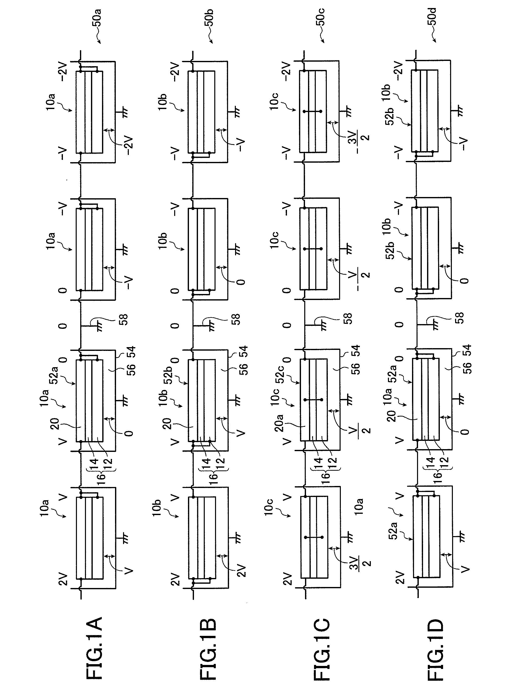
[0059]FIGS. 1A through 1D are circuit diagrams respectively schematically illustrating an embodiment of the solar cell device of the present invention. Note that although the representative example of the metal substrate with an insulation layer described below uses a metal substrate with an insulation layer in which an anodized film is formed as an insulation film on at least one surface of an aluminum (Al) base, the present invention is by no means limited to this particular configuration, as shall be described below.

[0060]The solar cell device 50a shown in FIG. 1A has four solar cell modules (referred to simply as “modules” below) 10a of the present invention connected in series; the solar cell device 50b shown in FIG. 1B has four solar cell modules 10b of the present invention connected in ser...


PUM


Abstract

The solar cell module and the solar cell device have excellent insulation properties, reduced fluctuation of leakage current and high withstand voltage. The solar cell module includes a metal substrate having a metal base and an insulation layer formed on at least one side of the metal base, and a semiconductor circuit provided on the metal substrate. The metal base is connected to a predetermined part of an electric path having a first potential between a minimum potential and a maximum potential of the semiconductor circuit, and a potential of the metal base is maintained at the first potential of the part of the electric path of the semiconductor circuit during the operation of the semiconductor circuit.

Description

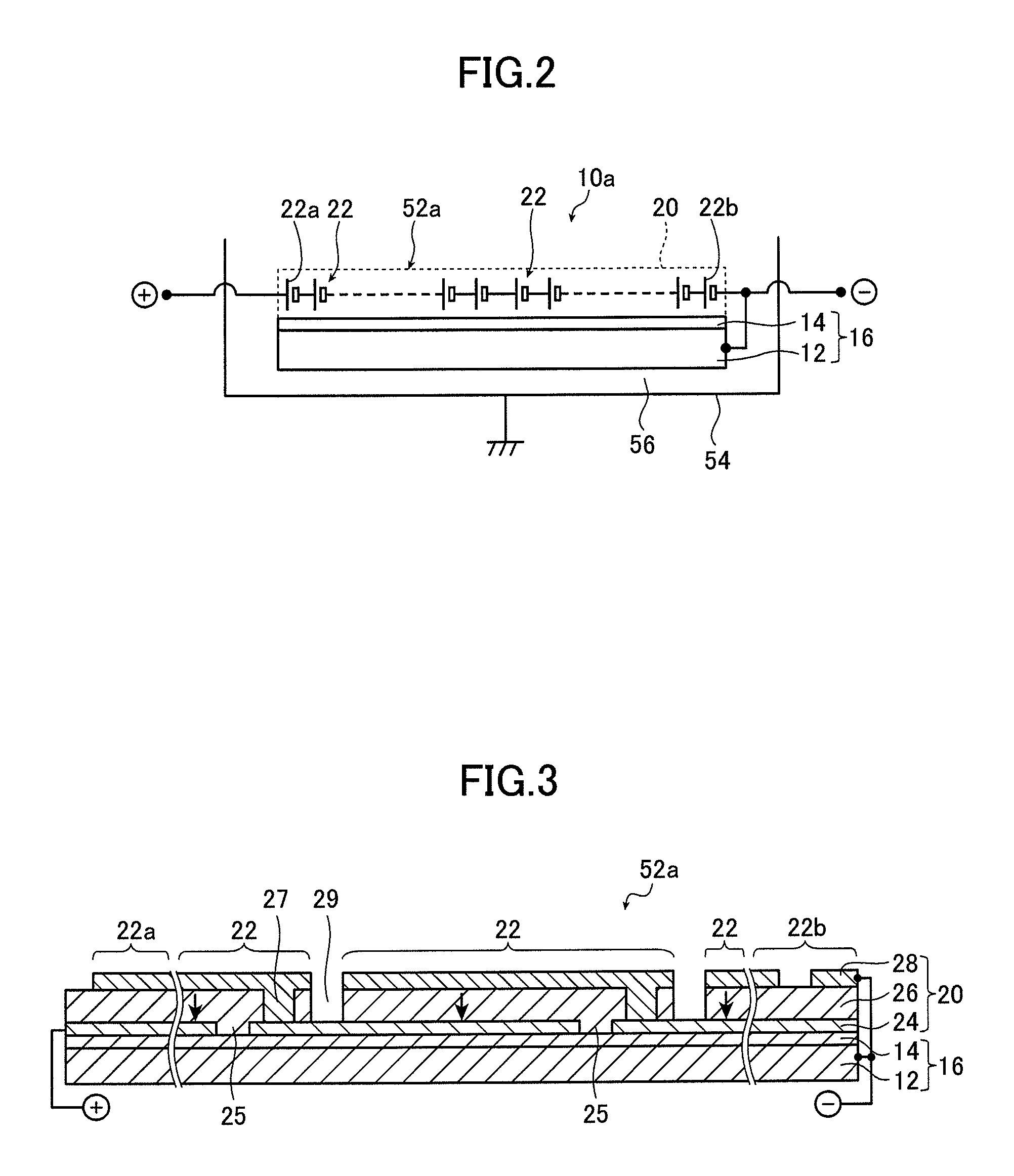
BACKGROUND OF THE INVENTION[0001]The present invention relates to a solar cell module and a solar cell device using the solar cell module provided with a semiconductor circuit on a metal substrate with an insulation layer as an insulation layer of insulation film such as anodized film on a metal base such as an aluminum (Al) base.[0002]There is currently intensive research being conducted on solar batteries in an effort to make improvements from various viewpoints. A solar battery comprises a number of solar cells connected in series on a substrate to form a semiconductor circuit, each of which solar cells is essentially composed of a laminate-structured semiconductor photoelectric conversion layer sandwiched by a lower electrode (back electrode) and an upper electrode (transparent electrode) for generating current by light absorption.[0003]Up to now, glass substrates are mainly used for solar cells, but use of flexible metal substrates is under investigation. There is a possibility...

Claims


Application Information

Patent Timeline
Patent Type & Authority Applications(United States)
IPC IPC(8): H01L31/05
CPCH01L31/0465Y02E10/541Y02E10/543H01L31/0504Y02E10/549Y02E10/542Y02E10/544H01L31/04H01L31/042
Inventor YAGO, HARUO
Owner FUJIFILM CORP
Learn More