
High fidelity through hole film, and associated method

Inactive Publication Date: 2011-09-08
THE UNIV OF NORTH CAROLINA AT CHAPEL HILL +2
View PDF20 Cites 16 Cited by
  • Summary
  • Abstract
  • Description
  • Claims
  • Application Information

AI Technical Summary

Benefits of technology

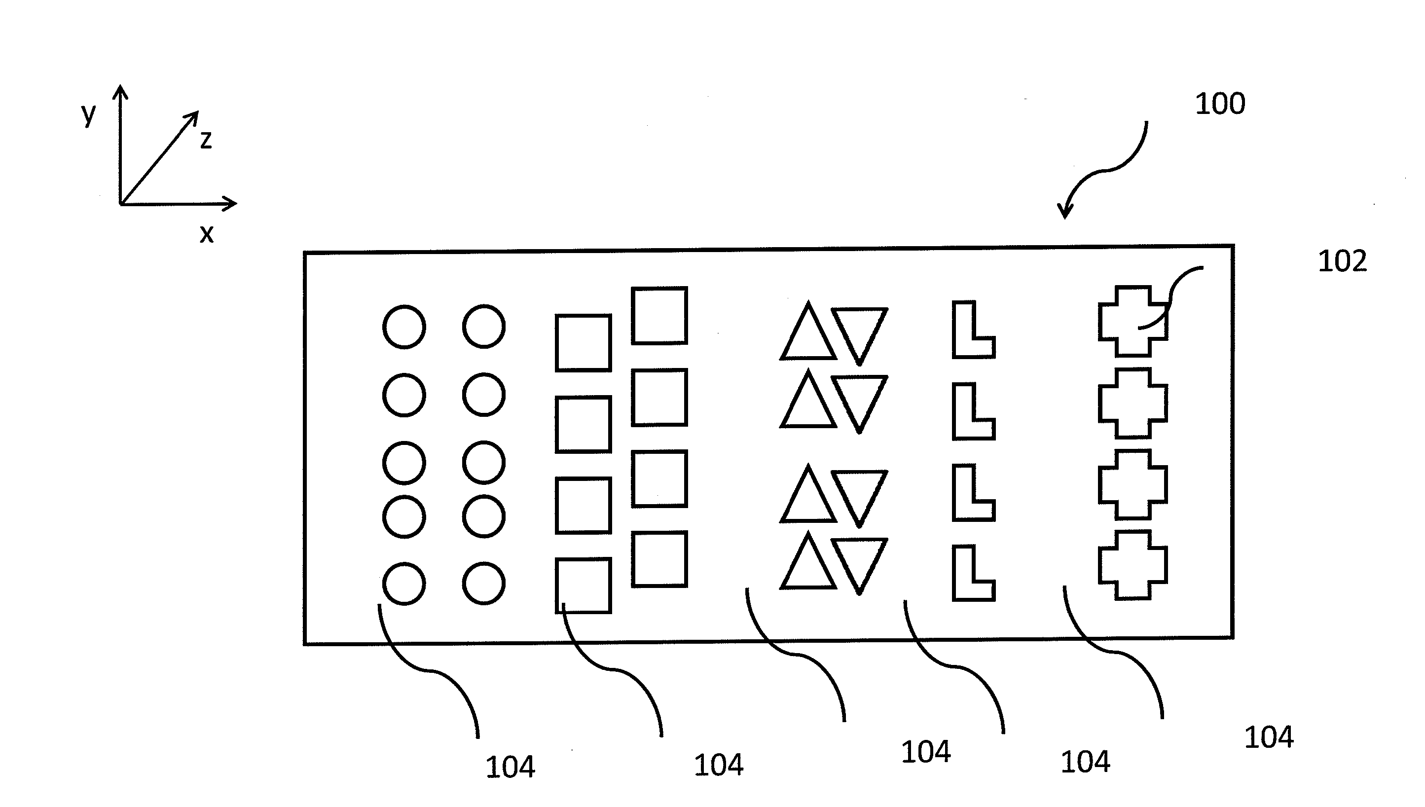
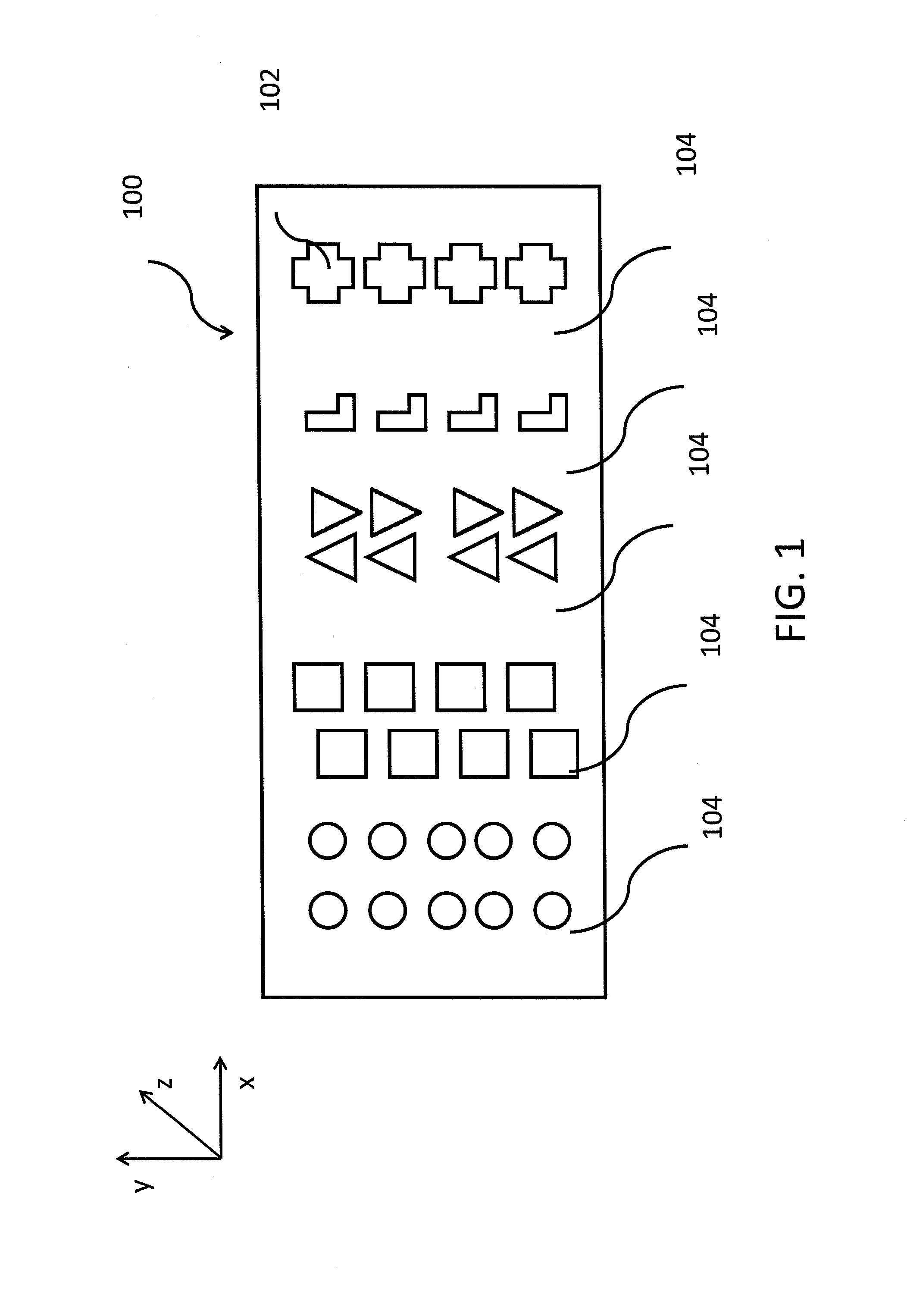
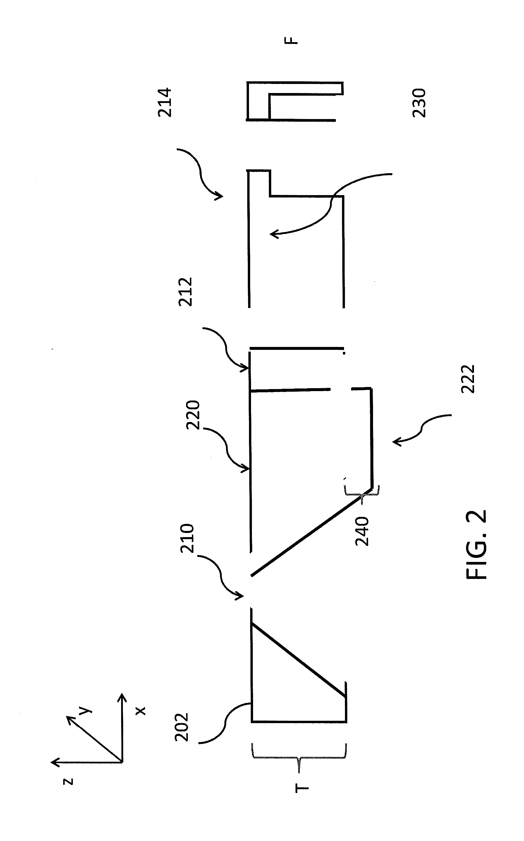
[0017]The above and other needs are met by the present invention which, in one embodiment, provides a membrane. Such a membrane comprises a first membrane layer having a first side and a second side. The first membrane layer defines a plurality of holes extending along a first axis between the first side and the second side. Each hole is defined by the first membrane layer as a complex three-dimensional shape, and each hole has a diameter of less than about 10 micrometers. The complex three dimensional shape of the present membrane can include a cone having an increasing diameter in a direction of flow across the membrane and/or nanometer fidelity features. The holes in the membrane can also be arranged in a predetermine order or spacing. In some embodiments, the plurality of holes includes a density of holes greater than about 80

Problems solved by technology

Although micron and submicron pore size filter membranes have some functionality they generally have limited porosity, discriminate principally on the basis of size alone, and often suffer from reduced flow rates due to blockage on the surface of the membrane.
Filters with micron or smaller scale pores, however, often have significant limitations.
However, track-etched membranes typically have low porosity, which limits the amount of throughput and filtration rates.
Attempts to increase porosity in track-etched filter membranes often result in doublets or triplets, which are holes that overlap and therefore reduce the discrimination of the filter membrane.
In addition to low porosity, track-etched membranes have another drawback.
The pores in track-etched membranes are limited to circular pores and are therefore not entirely suitable for filtration based on non-circular particle shape or shape alone.
One drawback, however, is that the manufacture of microstructures such as single-layer filter membranes by microlithography, micromachining, or similar processes suffers from several constraints.
As a result, very thin membranes are typically very fragile and may not be sufficiently robust for many applications.
A drawback of typical membrane systems is that on the one hand, finer filtration requirements typically demand a filter membrane that is increasingly thin and thus increasingly fragile; however, on the other hand, the desire for membrane robustness has generally been met only by thicker membranes that do not typically permit the formation of high porosity very small precisely controlled pores.
Although such a membrane may be suitable for some applications, it does not overcome limitations of the current art.
Another prior art membrane includes very thin microporous membranes having micron-scale pores, however, these devices are utilized in non-filtration applications.

Method used


Image

  • High fidelity through hole film, and associated method
  • High fidelity through hole film, and associated method
  • High fidelity through hole film, and associated method

Examples


example 1

[0069]An SU-8 photo-resist (PR) master with 110 um (length) by 110 um (width) by 50 um (height) features were used to make Fluorocur® (FCR) through membranes. A 50% solution of FLUOROCUR® (Liquidia Technologies, Inc., Durham, N.C.) resin with 0.1% 2,2-diethoxyacetophenone (DEAP) as photo-initiator in solkane (1,1,1,3,3-pentafluorobutane) was spin coated onto the PR master at 500 rpm for 1 min. The concentration of the solution and spin rate were controlled so that the resulting FCR layer is lower than the feature height of the PR master. Solkane evaporated during spin-coating. The thin layer of FCR on PR master was cured by 365 nm UV light for 2 min without nitrogen flow followed by 3 min with nitrogen purge. To help release the cured FCR through-hole membrane, a layer of norland optical adhesive (NOA) was laminated between the FCR membrane and PET substrate. After curing NOA74 by exposing to 365 nm UV for 4 min with nitrogen purge, the FCR through-hole membrane was removed from the...

example 2

[0070]A photo-resist (PR) master with 50 um (length) by 50 um (width) by 65 um (height) features were used to make Fluorocur® (FCR) through membranes. A 50% solution of FLUOROCUR® (Liquidia Technologies, Inc., Durham, N.C.) with 0.1% 2,2-diethoxyacetophenone (DEAP) as photo-initiator in 1,1,1,3,3-pentafluorobutane (solkane) was spin coated onto the PR master at 500 rpm for 1 min. The concentration of the solution and spin rate were controlled so that the resulting FCR layer is lower than the feature height of the PR master. Solkane evaporated during spin-coating. The thin layer of FCR on PV master was cured by 365 nm UV light for 2 min without nitrogen flow and 3 min with nitrogen purge. To help release the cured FCR through-hole membrane, a layer of norland optical adhesive (NOA) was laminated between the FCR membrane and PET substrate. After curing NOA74 by exposing to 365 nm UV light for 4 min with nitrogen purge, the FCR through-hole membrane was removed from the PR master and t...

example 3

[0071]A regular FCR mold was first prepared from the 110 um (length) by 110 um (width) by 50 um (height) SU-8 photoresist (PR) master. This FCR mold was used to make a NOA74 submaster. To do so, NOA74 was laminated between flat glass and the FCR mold and cured by 365 nm UV light for 4 minutes with nitrogen purge. The NOA74 submaster was obtained after removal of the FCR mold. This submaster was then used to make through hole membranes. A 50% solution of FLUOROCUR® (Liquidia Technologies, Inc., Durham, N.C.) with 0.1% 2,2-diethoxyacetophenone (DEAP) as photo-initiator in 1,1,1,3,3-pentafluorobutane (solkane) was spin coated onto the sub-master at 500 rpm for 1 min. The concentration of the solution and spin rate were controlled so that the resulting FCR layer is lower than the feature height of the sub-master. Solkane evaporated during spin-coating. The thin layer of FCR on PV master was cured by 365 nm UV light for 2 min without nitrogen flow and 3 min with nitrogen purge. The cured...


PUM

PropertyMeasurementUnit
Fractionaaaaaaaaaa
Fractionaaaaaaaaaa
Fractionaaaaaaaaaa

Abstract

A membrane is provided, comprising a first membrane layer having a first side and a second side. The first membrane layer defines a plurality of holes extending along a first axis between the first side and the second side. Each hole is defined by the first membrane layer as a complex three-dimensional shape, and each hole has a diameter of less than about 10 micrometers. The membrane is fabricated by dispersing a liquid polymeric material onto a patterned master template, hardening the polymeric material, and removing it from the master template. The membrane includes through holes which correspond to the structures of the patterned master template in size, cross-sectional and three dimensional shape, orientation, and the like.

Description

FEDERALLY SPONSORED RESEARCH OR DEVELOPMENT[0001]This disclosure was partially made with U.S. Government support under contract number N00014-02-1-0185 and N00014-07-1-0269 awarded by the United States Office of Naval Research and under contract number CHE-9876674 awarded by the National Science Foundation. The U.S. Government may have certain rights in the disclosure.BACKGROUND[0002]1. Technical Field[0003]Generally, the present disclosure relates to through hole masks and membranes, and more particularly, to membranes defining through holes having precision size and shape characteristics in three dimensions.[0004]2. Description of Related Art[0005]Filters that discriminate based on size and / or shape are well-known. One type of filter, for example, provides a tortuous path through which particles must navigate to pass through the filter. These are sometimes referred to as depth filters, and typically use a filter element made of a thick bed of fiber or other material. Due to their ...

Claims


Application Information

Patent Timeline
IPC IPC(8): B01D69/00B01D39/00B01D71/06B29C33/42
CPCB01D39/1692B01D2323/12B01D67/002
Inventor ZHOU, ZHILIANMENG, XIANSHENGDESIMONE, JOSEPH M.MAYNOR, BENJAMINROLLAND, JASONWILES, KENTON B.
Owner THE UNIV OF NORTH CAROLINA AT CHAPEL HILL
Learn More