Particle beam device and method for operation of a particle beam device

a particle beam and beam technology, applied in the direction of instruments, electrical devices, material analysis, etc., can solve problems such as affecting the efficiency of detectors, and achieve the effect of high detector efficiency

Inactive Publication Date: 2011-09-08
CARL ZEISS MICROSCOPY GMBH
View PDF31 Cites 10 Cited by
  • Summary
  • Abstract
  • Description
  • Claims
  • Application Information

AI Technical Summary

Benefits of technology

[0025]In a further embodiment of the particle beam device according to the system described herein, not only may the detector additionally or as an alternative to this be arranged in a cavity in a single hollow body, but the detector may be arranged in a plurality of hollow bodies. This embodiment of the particle beam device therefore may have a second hollow body with a second cavity. The second hollow body may be at a second hollow body potential. A second hollow body voltage may be a fifth potential difference between the second hollow body potential and the sample potential. The second hollow body voltage may be set by a fifth voltage supply unit. The first hollow body and the second hollow, body may, for example, be in the form of tubular electrodes. In particular, the second hollow body may be held in the first cavity in the first hollow body. The detector may then be held in the second cavity in the second hollow body. The first hollow body potential and the second hollow body potential may be of the same magnitude. In alternative embodiments, the first hollow body potential and the second hollow body potential may be of different magnitudes. Analyses have shown that an extraction field may be generated by a suitable choice of the first hollow body potential and of the second hollow body potential, taking account of the already previously mentioned sample potentials, the terminating electrode potential, the detector potential and / or the control electrode potential, such that a high detector efficiency is achieved. A sufficient number of first interaction particles and / or second interaction particles may pass through the first inlet opening in the first cavity and through the second inlet opening in the second cavity, and may be detected by the detector.

Problems solved by technology

This can lead to the extraction field being inadvertently changed, thus influencing the detector efficiency.

Method used


Image

  • Particle beam device and method for operation of a particle beam device
  • Particle beam device and method for operation of a particle beam device
  • Particle beam device and method for operation of a particle beam device

Examples


Embodiment Construction

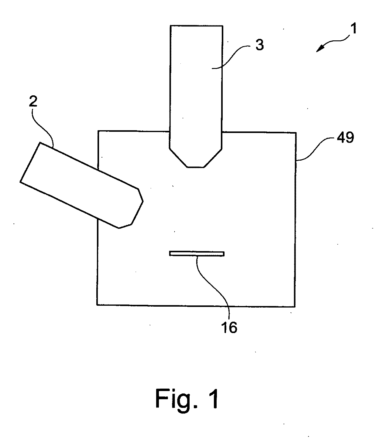
[0045]FIG. 1 shows a schematic illustration of one embodiment of a particle beam device 1 according to the system described herein. The particle beam device 1 has a first particle beam column 2 in the form of an ion beam column, and a second particle beam column 3 in the form of an electron beam column. As an alternative to this, both the first particle beam column 2 and the second particle beam column 3 may each be in the form of an ion beam column. The first particle beam column 2 and the second particle beam column 3 are arranged on a sample chamber 49 in which a sample 16 to be examined is arranged.

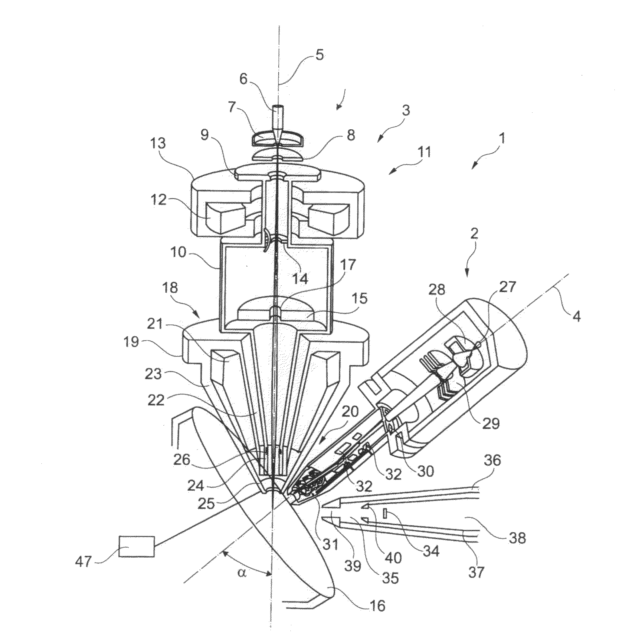
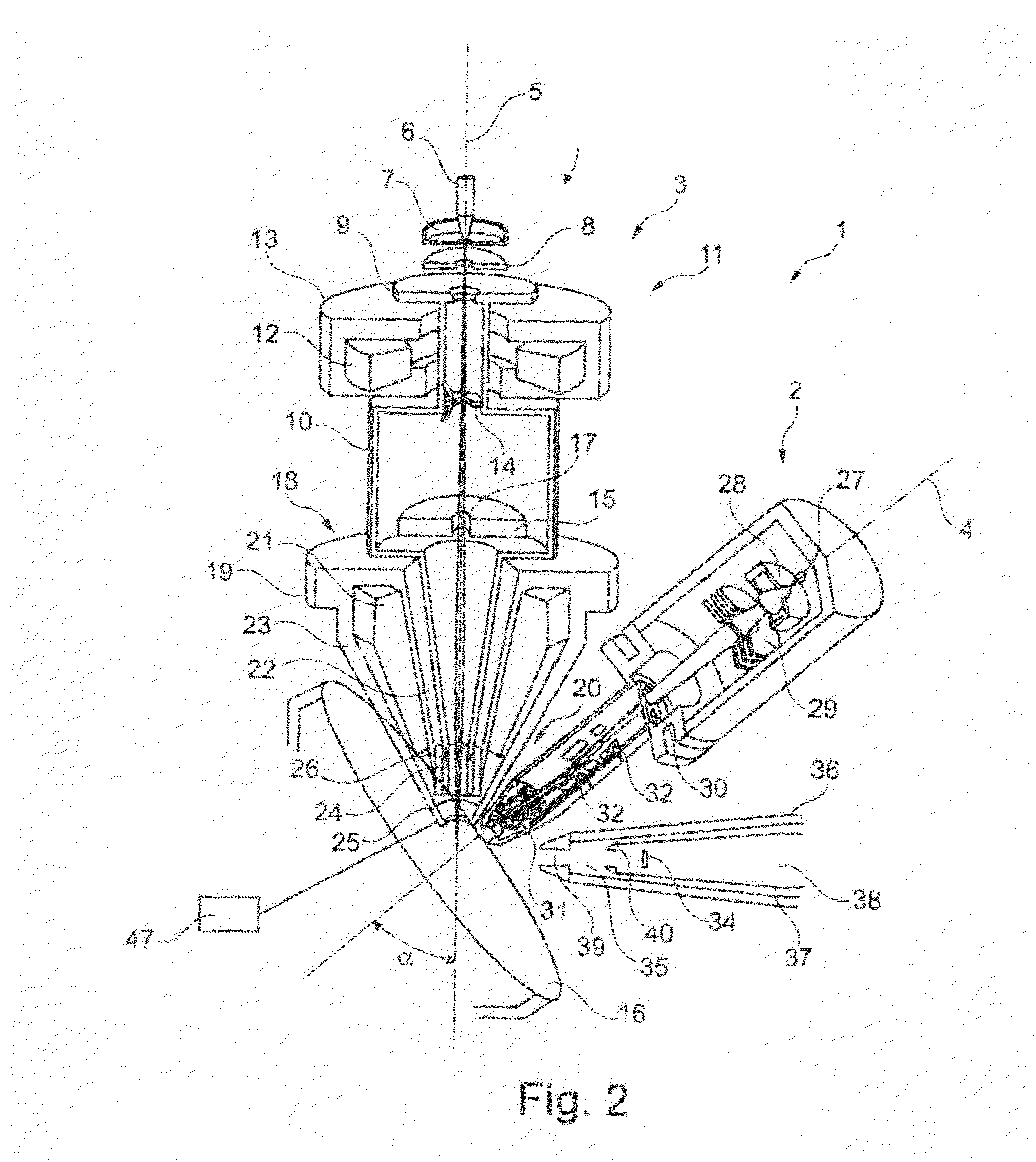
[0046]FIG. 2 shows a more detailed illustration of the particle beam device 1 as shown in FIG. 1. The sample chamber 49 is not illustrated, for clarity reasons. The first particle beam column 2, in the form of the ion beam column, has a first optical axis 4. Furthermore, the second particle beam column 3, in the form of the electron beam column, has a second optical axis 5.

[0047]The f...


PUM


Abstract

A particle beam device and a method for operation of a particle beam device are disclosed. The particle beam device has a sample chamber, a sample arranged in the sample chamber, a first particle beam column, a second particle beam column and at least one detector arranged in a first cavity in a first hollow body. The first cavity has a first inlet opening. The first particle beam column and the second particle beam column are arranged on one plane, while the detector is not arranged on that plane. At least one control electrode is arranged on the first particle beam column. The second particle beam column has a terminating electrode. A first hollow body voltage, a control electrode voltage and/or a terminating electrode voltage are/is chosen such that first interaction particles and/or second interaction particles enter the first cavity in the first hollow body through the first inlet opening.

Description

TECHNICAL FIELD[0001]This application relates to a particle beam device and to a method for operation of a particle beam device.BACKGROUND OF THE INVENTION[0002]Electron beam devices, in particular a scanning electron microscope (also referred to in the following text as SEM) are used to examine samples, in order to obtain knowledge about the characteristics and behavior of these samples in specific conditions.[0003]In the case of an SEM, an electron beam (also referred to in the following text as the primary electron beam) is generated by a beam generator, and is focused by a beam guidance system, in particular an objective lens, onto a sample to be examined. The primary electron beam is passed over a surface of the sample to be examined, in the form of a raster, by a deflection device. The electrons in the primary electron beam in this case interact with the material of the sample to be examined. The interaction results in particular in interaction particles. In particular, electr...

Claims


Application Information

Patent Timeline
Patent Type & Authority Applications(United States)
IPC IPC(8): H01J37/28
CPCH01J37/05H01J37/28H01J37/244H01J37/145
Inventor PREIKSZAS, DIRK
Owner CARL ZEISS MICROSCOPY GMBH
Why Eureka
Try Eureka