Machine tool

a technology of machine tools and clamping tools, which is applied in the field of machine tools, can solve the problems of not reaching such high holding forces, high cost of hydraulic lines that have to withstand a rather high pressure (several hundred bars), and the installation of hydraulic lines that have to withstand a rather high pressure (100 bars) is expensive, and achieves high contact pressure. , the effect of high pressure for clamping work pieces

Inactive Publication Date: 2011-09-08
GROB WERKE & K G
View PDF14 Cites 8 Cited by
  • Summary
  • Abstract
  • Description
  • Claims
  • Application Information

AI Technical Summary

Benefits of technology

[0051]A favorable modification also provides that the clamping elements and / or the collet chucks are designed hydraulically acting, wherein the pressure-generating hydraulic pump is provided directly at or in the clamping element or at or in the collet chuck. In the beginning, the advantage of such a solution has already been described as it is not necessary in such a design to supply the expensive hydraulic aggregates or to connect them by pipes or hoses. According to the solution the electric motor drives a hydraulic pump generating pressure that is arranged directly in or at the clamping element. Thus, only a connection from the hydraulic pump, if necessary, to the pressure cylinder, at the clamping means has to be produced that can be provided directly as boring in the clamping element or in the collet chuck. Thus quasi the hydraulic element is installed in the last possible element during the clamping process, namely in the collet chuck or in the clamping means itself. The expensive piping and / or providing of suitable hose connections, distributors and the like is dropped completely. It is not necessary here, either, to provide suitable, flexible elements that have to compensate swiveling of the machining plane. Nevertheless, the hydraulic system provides, as a rule, slightly higher pressure for clamping the work pieces.
[0052]According to this the solution achieves that at or in the clamping element a hydraulic pump is provided acting independently from a central hydraulic aggregate and generating directly at or in the clamping element the required contact pressure for clamping the work pieces or the tools. This is an advantageous solution because—as already mentioned—the high contact pressure can be generated directly in or at the clamping element.

Problems solved by technology

However, it is a disadvantage that installing the hydraulic lines that have to withstand a rather high pressure (several 100 bars) is expensive The hydraulic lines also require, because of the high stress, appropriate maintenance.
However, often the work piece table can also rotate in the space, and also in these swiveled positions a reliable hydraulic supply has to be guaranteed what can be reached with these mentioned rotatable elements only with a considerable effort for construction as well as for maintenance.
Alternatively, the use of pneumatic work piece clamping systems is known, however, these do not reach such high holding forces.
There is also the problem that position interrogations, for example is the work piece clamped or the machining tool clamped, can only be interrogated indirectly via the pressure or other expensive installations.
Eventually, also the effort for apparatus for installing the hydraulic arrangement is considerable, as besides a piping and installation of fitting hoses or flexible pipes also an appropriate pump aggregate as well as valves and selecting of the valves are required.

Method used


Image

  • Machine tool
  • Machine tool
  • Machine tool

Examples


Embodiment Construction

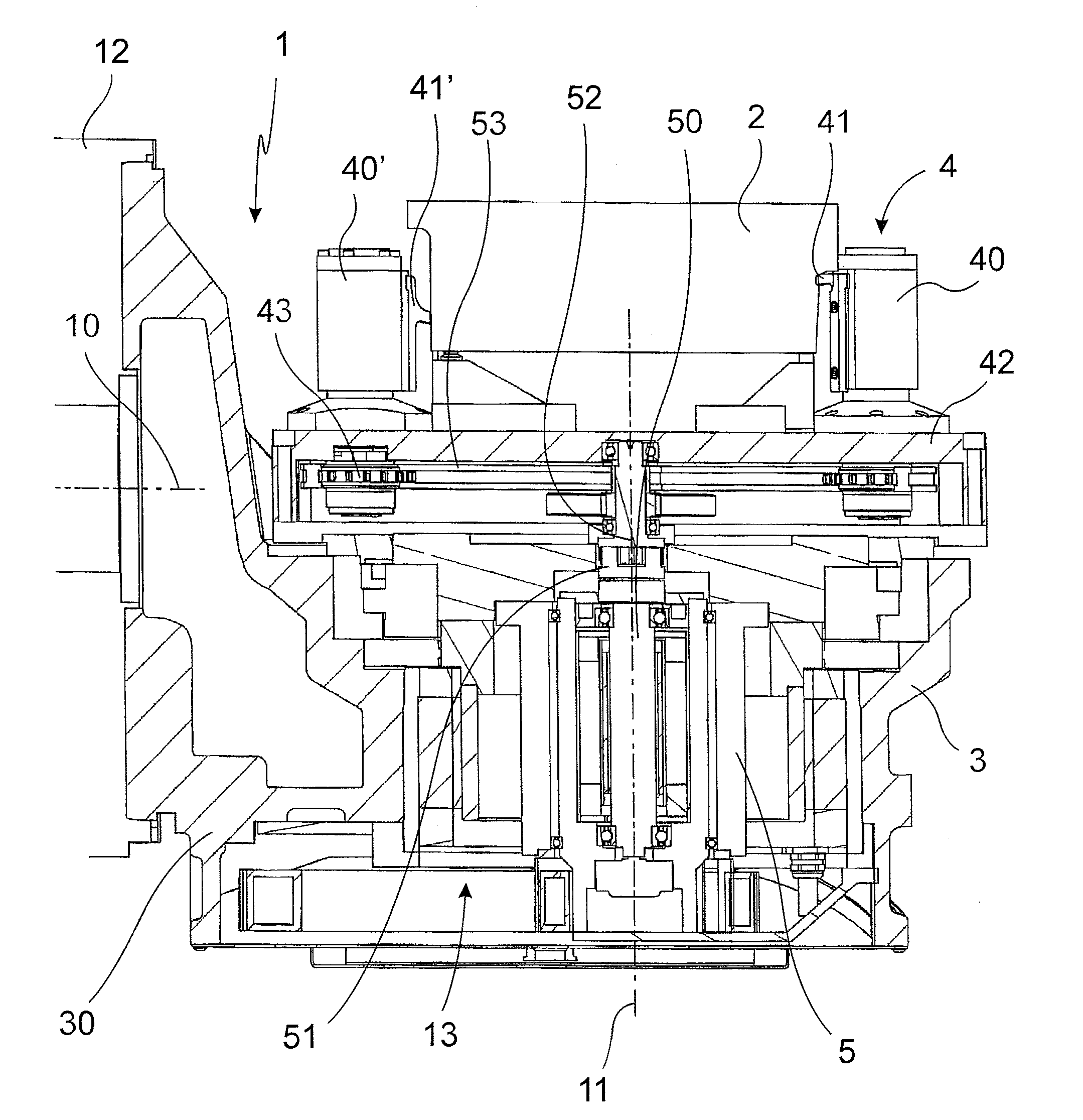
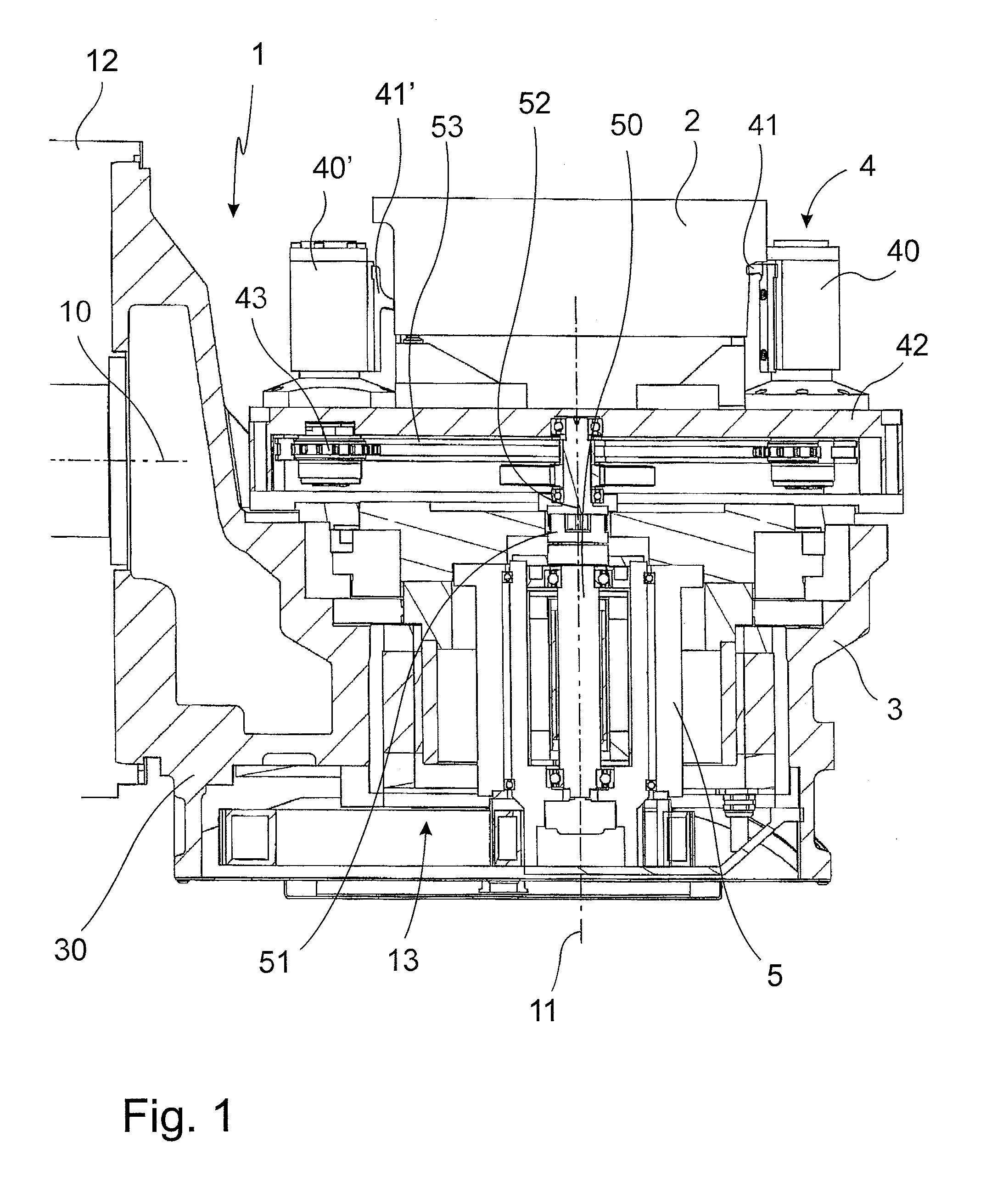
[0069]FIG. 1 shows the invention schematically. The machine tool 1 comprises, on the one hand, a work piece table 3, holding the work piece 2. FIG. 1 does not show the machining tool designed, for example, as drill or milling cutter, driven by a tool spindle and moving in an appropriate way relatively to the work piece 2. The machine tool 1 according to the invention has a number of axes. For a machining as flexible as possible it is provided that the work piece 2 can be positioned relatively to the machining tool along the three spatial axes. Besides these longitudinal axes, however, also rotational axes are provided. A first rotational axis is indicated by reference number 10 and is called B-axis. It makes a rotation of the work piece table 3 around a horizontally orientated rotational axis 10 possible. The arrangement is here chosen in such a way that the work piece table 3 has a console 30 arranged, for example, on one side on a slide or pillar 12. If the design is slide-like, f...


PUM

PropertyMeasurementUnit
pressureaaaaaaaaaa
angleaaaaaaaaaa
angleaaaaaaaaaa

Abstract

The invention refers to a machine tool for machining one or more work pieces, wherein the work piece is held indirectly or directly by a clamping device in the machine tool on or at a non-rotary work piece table or a work piece table rotating around at least one axis.
The invention is characterized in that the clamping device comprises at least one clamping element interacting indirectly or directly with the work piece, and an electric motor is provided for generating the clamping power that is in active connection with the clamping element.

Description

BACKGROUND OF THE INVENTION[0001]The invention refers to a machine tool for the machining of one or more work pieces, wherein the work piece is held indirectly or directly in the machine tool on or in a non-rotatable work piece table or a work piece table in particular rotatable around one axis.[0002]The invention comprises furthermore also a machine tool for the machining of one or more work pieces with a non-rotatable machining tool or in particular by a machining tool driven rotary by a tool spindle, wherein the machining tool is held in a tool mounting indirectly or directly by a tool clamping device.[0003]The machine tools of this kind are, for example, part of more complex, in particular metal cutting machining lines, or also realized in preferably flexibly used machining centers. The machine tools of this kind have, as a rule, a high rotational speed of the metal-cutting machining tools. Also the other forces occurring during machining are actually considerable, so that for a...

Claims


Application Information

Patent Timeline
Patent Type & Authority Applications(United States)
IPC IPC(8): B23Q3/02
CPCB23Q3/06B23Q1/0009B23Q1/76B23Q5/04B23Q5/22B23Q2703/02B23Q2703/12B24B1/04
Inventor GROB, BURKHART
Owner GROB WERKE & K G
Why Eureka
Try Eureka