System, network protector enclosure, and automatic racking system

a technology of automatic racking and enclosure, applied in the field of network protectors, can solve the problems of equipment damage, serious bodily injury or even death, large ppe, hot and uncomfortable, etc., and achieve the effect of improving worker safety

Active Publication Date: 2011-09-08
EATON INTELLIGENT POWER LTD
View PDF14 Cites 15 Cited by
  • Summary
  • Abstract
  • Description
  • Claims
  • Application Information

AI Technical Summary

Benefits of technology

[0020]This need and others are met by embodiments of the disclosed concept, which provide a racking mechanism that works in isolation with the door of the network protector enclosure being safely closed. This provides the worker with complete protection from exposure to energized bus work, which is internal to the network protector enclosure. Due to the nature of network systems with relatively high available secondary fault current, keeping users out of the enclosed space of a network protector vault environment greatly improves worker safety.

Problems solved by technology

However, actuation of the draw-out mechanism requires direct user involvement in the environment of the network protector vault.
However, as a result, the worker can be exposed to arc flash hazards, which can cause equipment damage, serious bodily injury or even death if done improperly.
Therefore, the workers are typically required to wear approved personal protection equipment (PPE) to resist serious injury or death that could result if an electrical failure were to occur during racking / draw-out / draw-in operations.
However, PPE is generally bulky, hot and uncomfortable, which dissuades workers from wearing it.
It is believed that remote automatic racking has never been used on network protectors.

Method used


Image

  • System, network protector enclosure, and automatic racking system
  • System, network protector enclosure, and automatic racking system
  • System, network protector enclosure, and automatic racking system

Examples


example 1

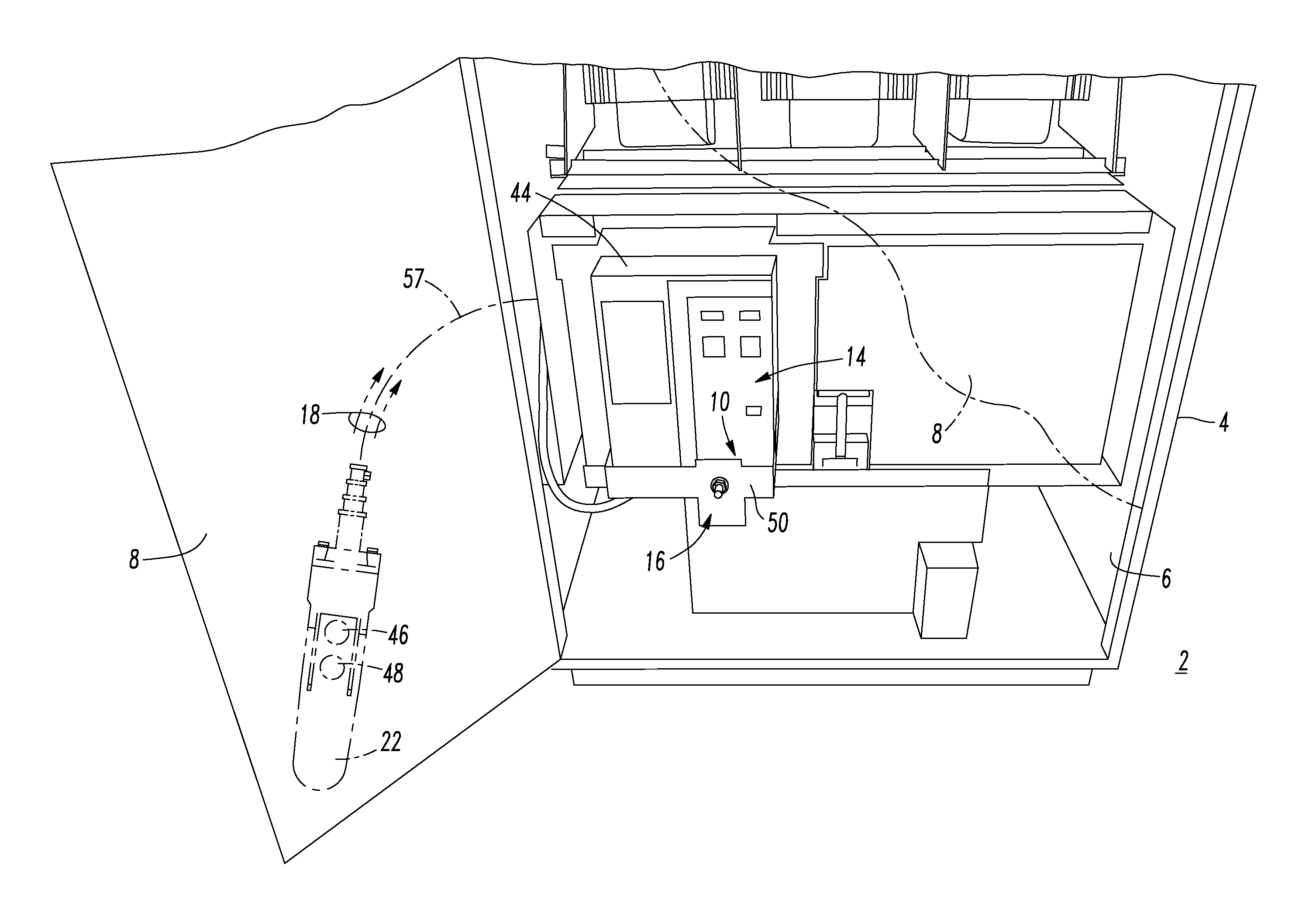
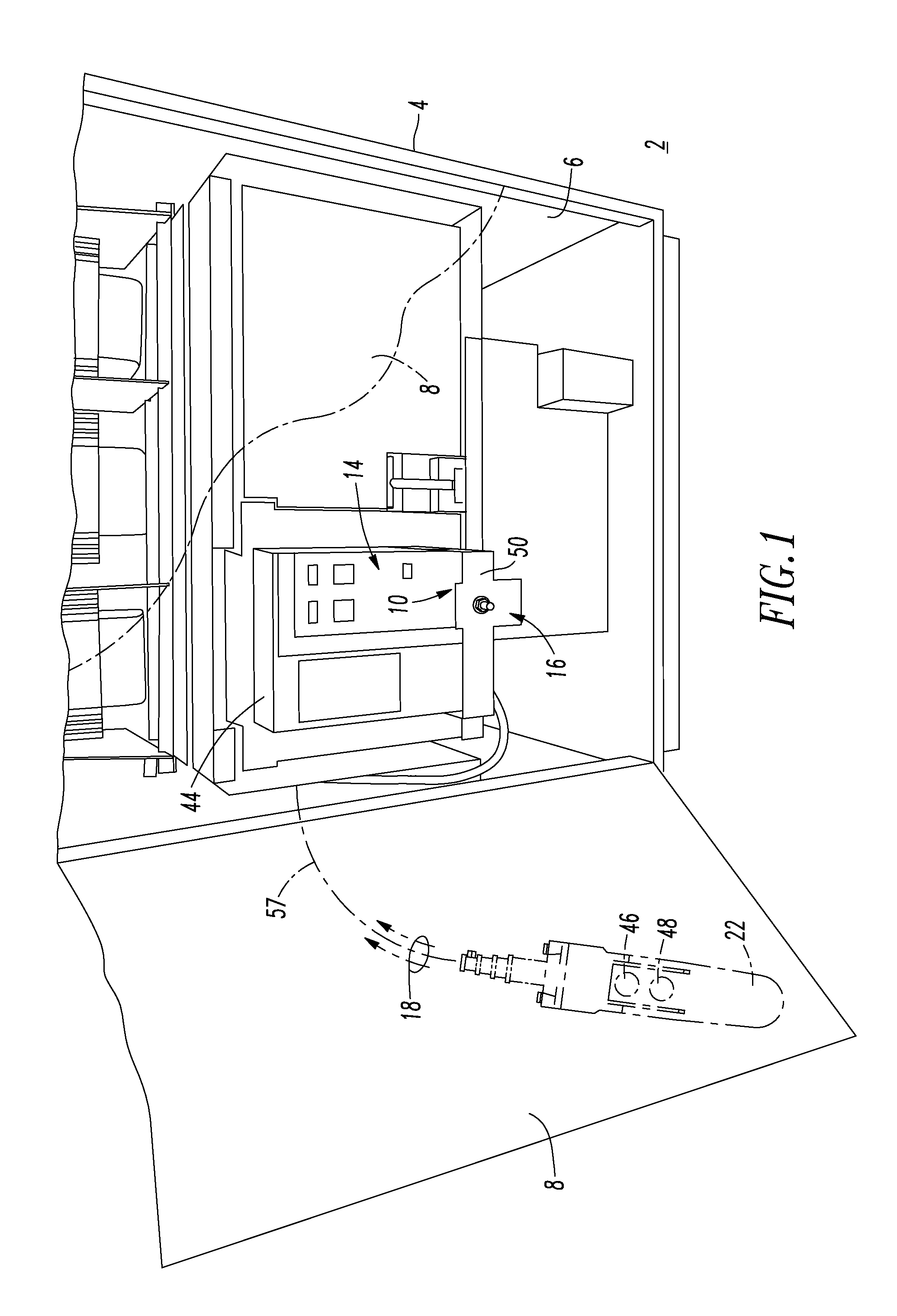
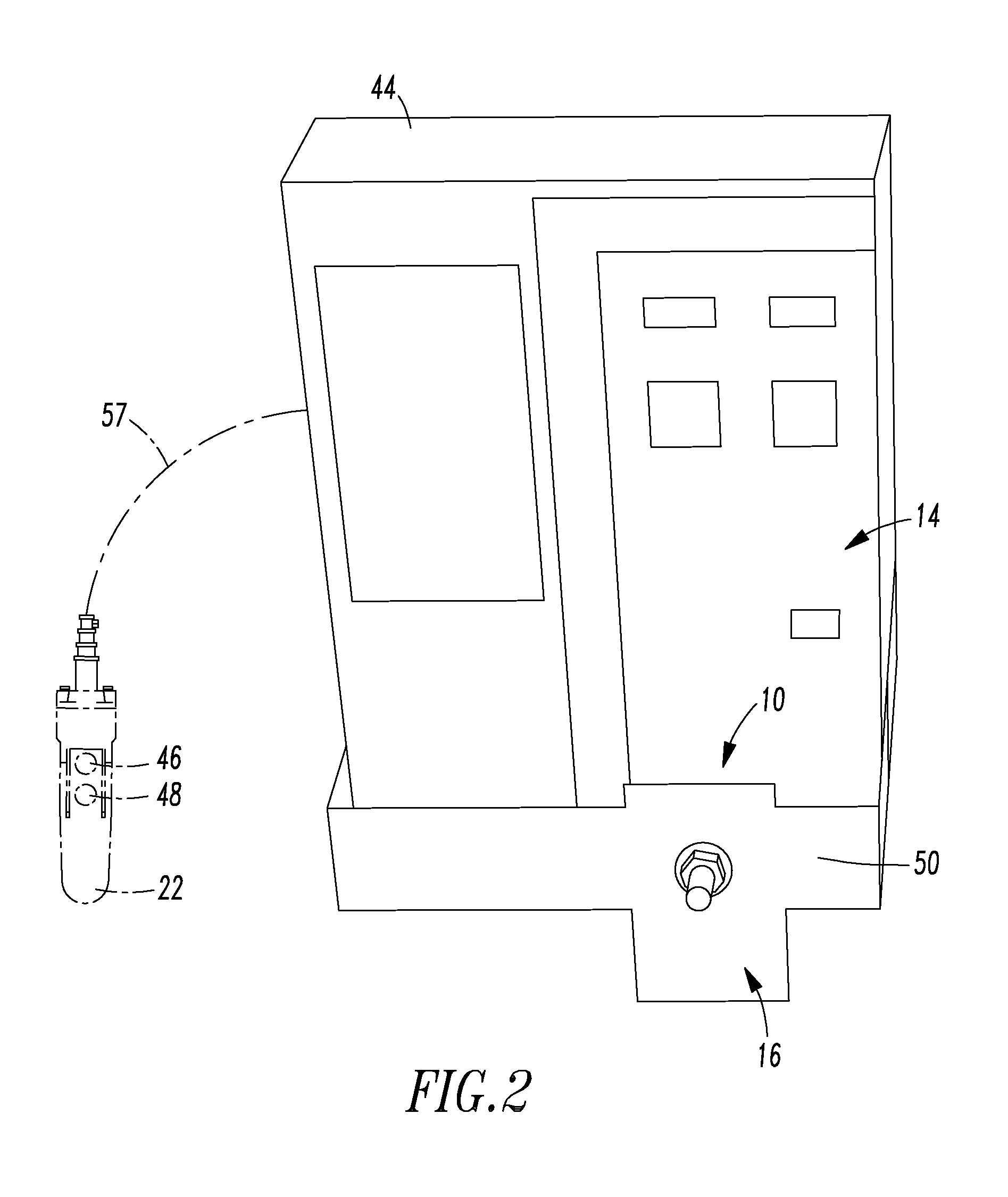
[0043]For example, the system 2 can be a network protector enclosure 2. The racking mechanism member 12 can be a lead screw 12 rotatable in a first rotational direction to a first position thereof and an opposite second rotational direction to a different second position thereof. The control mechanism 16 can be a remote control mechanism 16 structured to rotate the lead screw 12 between the first position and the different second position thereof responsive to the number of remote commands 18.

example 2

[0044]The remote control mechanism 16 can include a controller 20 (FIG. 3), such as a processor, and a user interface 22 (shown in phantom line drawing in FIG. 1) cooperating with the controller 20 to provide the number of remote commands 18. The controller 20 can be structured to cooperate with the remote user interface 22, which provides the number of remote commands 18. Alternatively, the controller 20 can be activated via a remote switch (not shown), from any suitable user interface, such as, for example, a pendant station (not shown), or by any suitable remote communications.

example 3

[0045]Referring to FIGS. 3-5, the remote control mechanism 16 can be an automatic racking system 24 including a motor 26 (FIG. 5) and a gear box assembly 28 driven by the motor 26. The gear box assembly 28 includes a number of gears 30, such as gear 32 having a position, an output shaft 33 driven by the number of gears 30, and a plurality of magnets 34 (FIG. 4) disposed about the gear 32. A sensor 36 is responsive to the plurality of magnets 34. The controller 20 includes an input 38 from the sensor 36, and an output 40 to power the motor 26. The controller 20 is structured to determine the position of the gear 32 from the sensor 36, and to control the motor 26 responsive to the number of remote commands 18 (FIG. 1).


PUM


Abstract

A system includes an electrical enclosure having an inner volume and a door structured to open to expose the inner volume and structured to close to enclose the inner volume. A racking mechanism is disposed in the inner volume and includes a member movable in a first direction to a first position and an opposite second direction to a different second position. A network protector is carried by the racking mechanism and is movable thereby between a connect position in the inner volume corresponding to the first position of the member of the racking mechanism, and a test position in the inner volume corresponding to the different second position of the member of the racking mechanism. A control mechanism is structured to move the member of the racking mechanism between the first position and the different second position of the member responsive to a number of remote commands.

Description

BACKGROUND[0001]1. Field[0002]The disclosed concept pertains generally to network protectors and, more particularly, to network protectors carried and movable by a racking mechanism. The disclosed concept further pertains to network protector systems. The disclosed concept also pertains to automatic racking systems for electrical switching apparatus.[0003]2. Background Information[0004]Circuit breakers for medium voltage switchgear apparatus applications are generally housed in metal enclosures and are removable. The apparatus typically includes at least one levering-in mechanism or device to move a circuit breaker between a disconnect position, in which the primary contacts of the circuit breaker are fully disengaged from the mating primary contacts within the enclosure, and a connect position, in which the primary contacts of the circuit breaker and enclosure are fully engaged. Levering-in and levering-out / withdrawing of a circuit breaker can be accomplished by using a detachable ...

Claims


Application Information

Patent Timeline
Patent Type & Authority Applications(United States)
IPC IPC(8): H05K5/00
CPCH02B11/127H05K5/00
Inventor FAULKNER, MARK A.ONEUFER, STEPHEN W.CASON, STEPHEN R.
Owner EATON INTELLIGENT POWER LTD
Why Eureka
Try Eureka