Surface structure modification

a surface structure and structure technology, applied in the field of surface structure modification, can solve the problems of unsuitable pulp chamber and root canal space for pulp chamber and root canal space for bacterial infection detection, and the technique does not allow for the identification of bacterial infection within the pulp chamber and root canal of teeth, and does not provide a controlled means for eliminating that infection

Active Publication Date: 2011-09-08
THE UNIV OF QUEENSLAND
View PDF18 Cites 47 Cited by
  • Summary
  • Abstract
  • Description
  • Claims
  • Application Information

AI Technical Summary

Benefits of technology

[0084]b) an optical fibre coupled to the optical system at a first end, a second end of the optical fibre including a tip, at least part of the tip having a conica...

Problems solved by technology

However, these techniques do not allow for the identification of bacterial infection within the pulp chambers and root canals of teeth.
However, this method and apparatus does not identify the presence location or extent of the bacterial infection in the root canal, nor does it provide a controlled means for eliminating that infection at the time of treatment.
The complex multi-element rigid optical tips typically employed with this device for detecting dental caries are unsuitable for use in the pulp chamber and root canal space because of their large diameter and length, and lack of flexibility.
Such metal waveguides h...

Method used


Image

  • Surface structure modification
  • Surface structure modification
  • Surface structure modification

Examples


Embodiment Construction

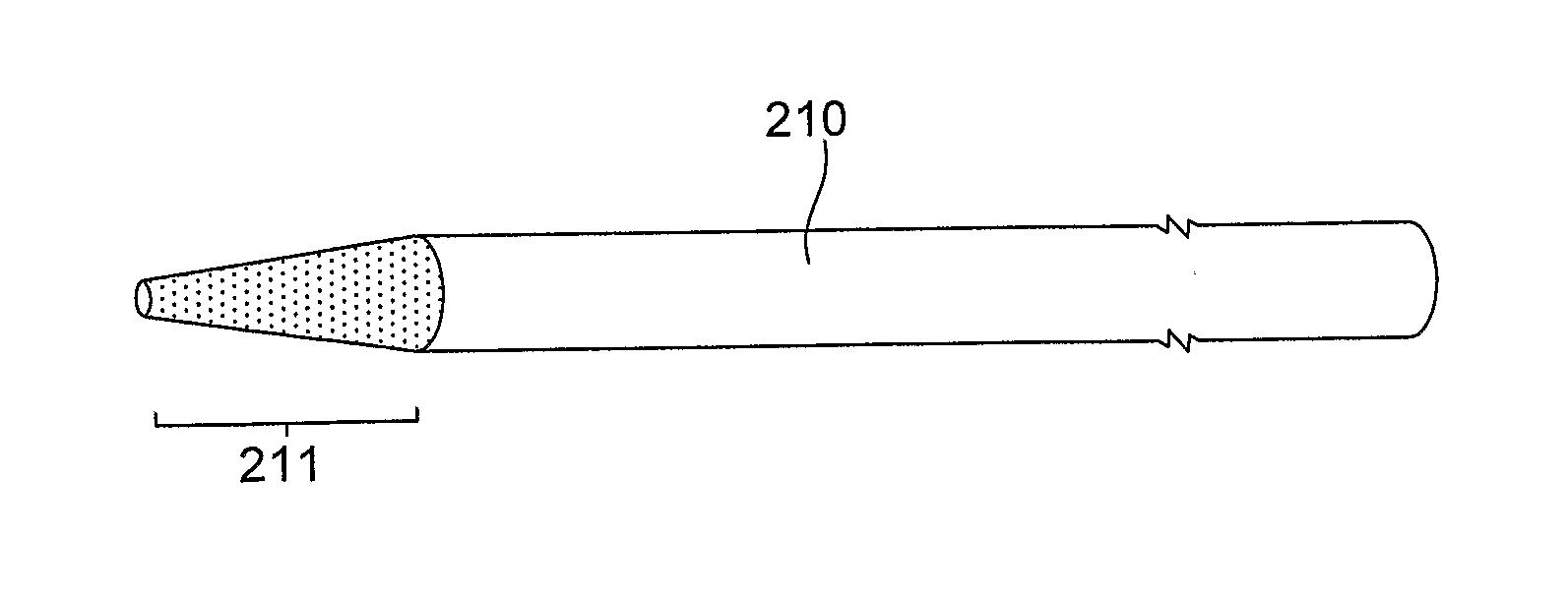
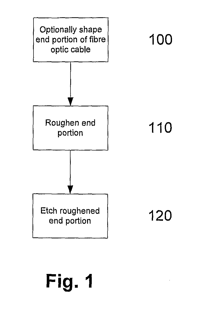
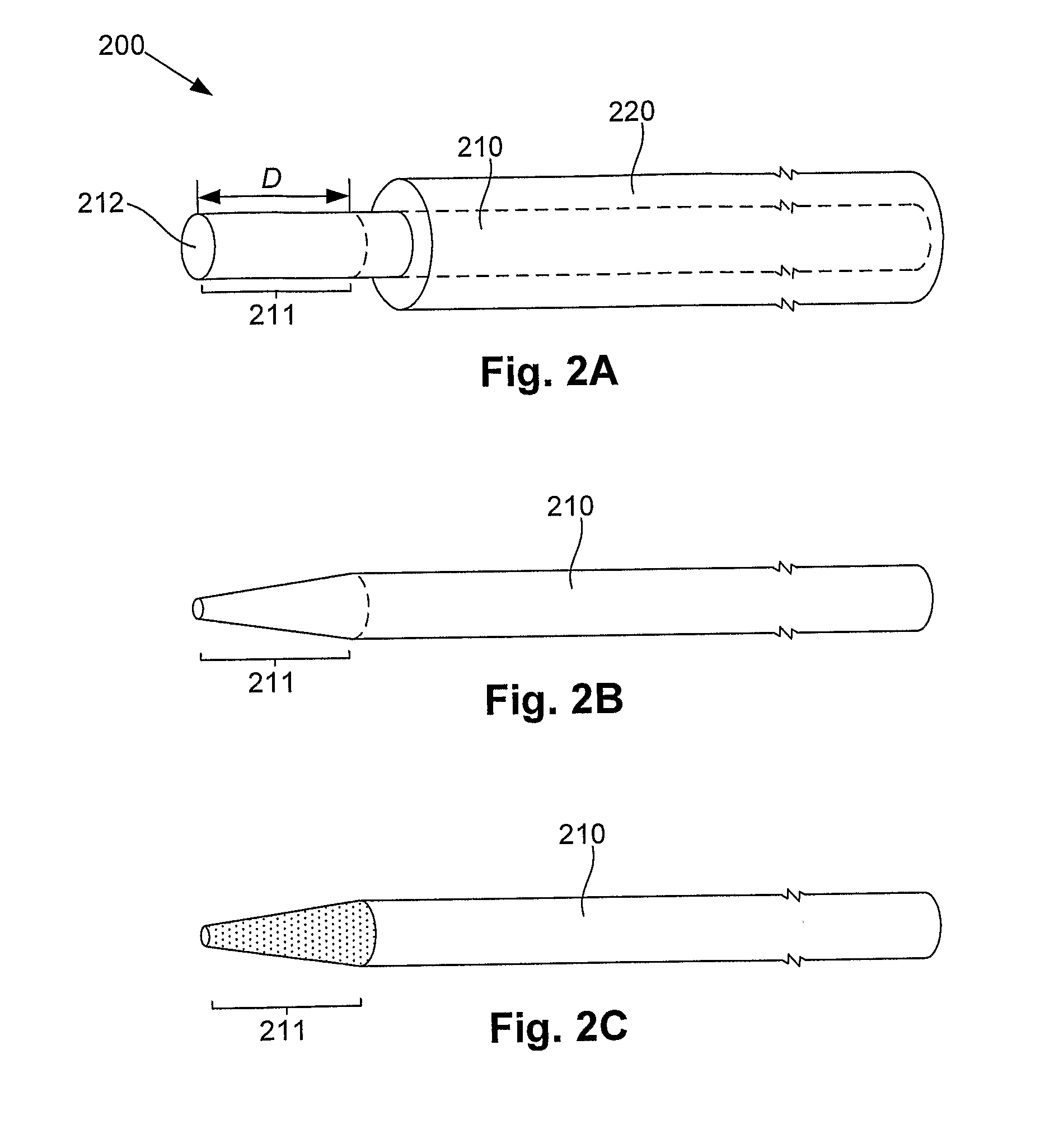
[0210]An example of a process for modifying the surface structure of a material to thereby modify the optical properties will now be described. For the purpose of this example, the process is used to produce an optical fibre tip as will now be described with reference to FIG. 1, and FIGS. 2A to 2C.

[0211]In this example, at step 100 an end portion of an optical fibre is optionally shaped. An example optical fibre 200 is shown in FIG. 2A. In this example, the optical fibre 200 includes a core material 210, such as a silica glass or the like, which may optionally be surrounded by a cladding 220, such as a protective polymer layer, or the like. In this example, the end portion 211 typically extends a distance D from an end 212 of the core 210. Typically the cladding 220 is removed to expose at least the end portion 211 and optionally for an additional part of the core 210 as shown.

[0212]The shaping can be of any suitable shape, and is typically selected so as to maximise the amount of r...


PUM

PropertyMeasurementUnit
Lengthaaaaaaaaaa
Lengthaaaaaaaaaa
Lengthaaaaaaaaaa

Abstract

A method of forming an optical fibre tip, the method including, roughening at least part of an end portion of the optical fibre; and, etching the roughed end portion to thereby form an optical fibre tip.

Description

BACKGROUND OF THE INVENTION[0001]The present invention relates to a method of modifying the surface structure of a material and in particular for forming an optical fibre tip suitable for emitting or detecting radiation. The present invention also relates to a method and apparatus for interaction with a part of a subject and in particular using an optical fibre tip for emitting or detecting radiation.DESCRIPTION OF THE PRIOR ART[0002]The reference in this specification to any prior publication (or information derived from it), or to any matter which is known, is not, and should not be taken as an acknowledgment or admission or any form of suggestion that the prior publication (or information derived from it) or known matter forms part of the common general knowledge in the field of endeavour to which this specification relates.[0003]Optical fibres are used in a range of different medical applications, typically for delivery of laser or other similar radiation to part of a subject, o...

Claims


Application Information

Patent Timeline
IPC IPC(8): A61B6/14G01J5/00G01N21/64G02B6/26B24B1/00A61B6/00A61N5/06C23F1/02
CPCA61C1/0046C03C25/626G02B6/262G01N21/64C03C25/68A61C5/40G01T7/00H01S3/00
Inventor WALSH, LAURENCE JAMESGEORGE, ROY
Owner THE UNIV OF QUEENSLAND
Why Eureka
Try Eureka