Method for moving a tool of a CNC machine over a surface

a technology of computer numerical control and moving tools, applied in the direction of instruments, electric digital data processing, special data processing applications, etc., can solve problems such as the danger of introducing measurement errors, and achieve the effect of accurate measurement of the actual surfa

Active Publication Date: 2011-09-08
FIDIA
View PDF22 Cites 24 Cited by
  • Summary
  • Abstract
  • Description
  • Claims
  • Application Information

AI Technical Summary

Benefits of technology

Changing the path based on the actual shape of the surface as determined during processing can provide a way of moving the tool over the surface wherein it is oriented to the surface in a way which is better suited for treating the surface in its actual shape.
In addition, determining the actual shape of the surface based on measurement values by a response

Problems solved by technology

In addition, determining the actual shape of the surface based on measurement values obtained by an additional tracking device (like a LASER) implies the dang

Method used


Image

  • Method for moving a tool of a CNC machine over a surface
  • Method for moving a tool of a CNC machine over a surface
  • Method for moving a tool of a CNC machine over a surface

Examples


Embodiment Construction

Exemplary embodiments according to the present disclosure are described in the following. In particular, the tool which is moved by a CNC machine is described as being a hammer in some embodiments. However, the invention is not limited to be applied to the tool being a hammer, nor is the invention limited to the described examples.

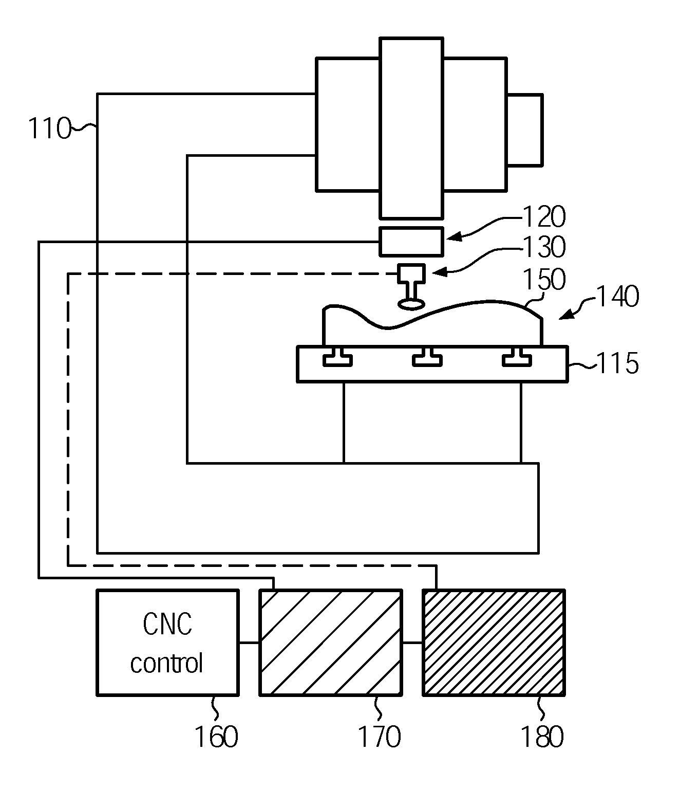
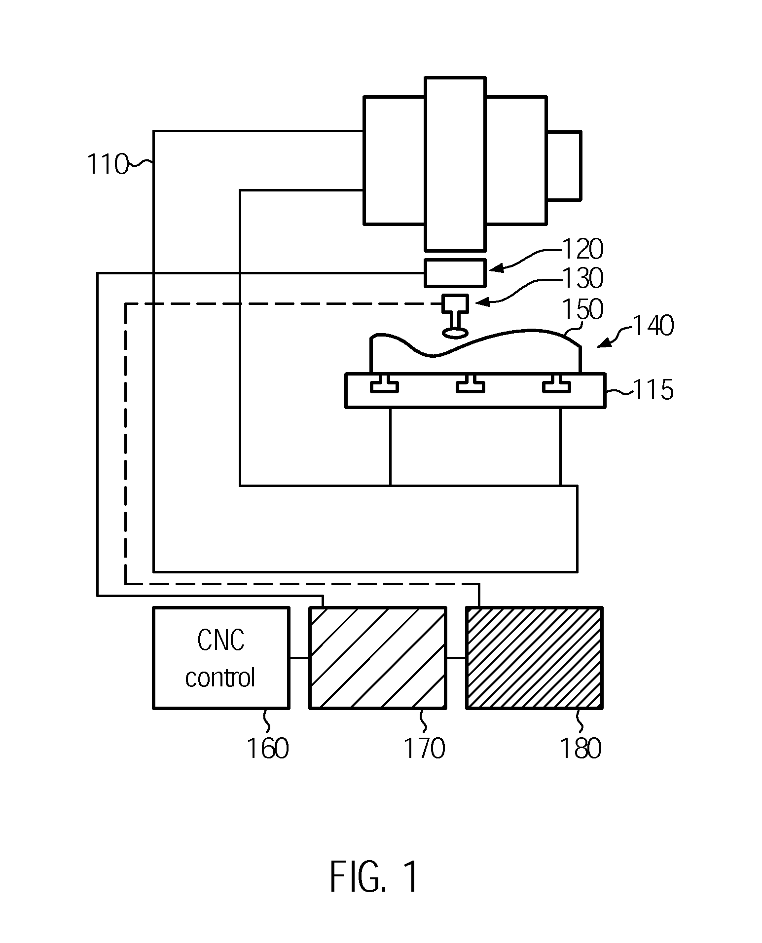
FIG. 1 illustrates an embodiment of a CNC machine in accordance with the present disclosure. The body 110 of the CNC machine comprises a stage 115 where a part 140 to be treated is mounted. The CNC machine is used to work on the surface 150 of the part 140.

The CNC machine also comprises a machining unit 120. The machining unit comprises a sensor unit of the CNC machine. The machining unit also comprises an actuator unit which carries the tool 130 which actually touches the surface 115 of the part 140 and performs work on the surface 115. The actuator unit may include a toolholder for carrying the tool 130.

The CNC machine moves the machining unit together w...


PUM


Abstract

A method for moving a tool of a CNC machine over a surface, wherein the CNC machine is provided with a sensor unit, comprising the steps of: (a) moving the tool over the surface in a predetermined direction and/or with a predetermined velocity and/or along a predetermined path, (b) treating the surface by the tool in accordance with a predetermined value of a treatment parameter, (c) determining, by the sensor unit, a response value indicating a response of the tool to treating the surface and/or to being pressed to the surface, and (d) determining a new direction and/or a new velocity and/or a new path and/or a new value for the treatment parameter based on the response value.

Description

CROSS-REFERENCE TO RELATED APPLICATIONSThis application claims foreign priority benefits under 35 U.S.C. §119(a)-(d) to European patent application number EP 10002317.5, filed Mar. 5, 2010, which is incorporated by reference in its entirety.TECHNICAL FIELDThe present disclosure is directed to a method for moving a tool of a computer numerical control (CNC) machine over a surface.BACKGROUNDWhile a tool is moved over the surface of a part by a CNC machine, the tool is, in general, performing some kind of treating on the part. The result of the treatment is dependent on treating the surface under optimal conditions, like treating the surface under predetermined angles and in preferred directions associated with the structure of the material. To achieve good results for treating, a preferred path for moving the tool during treating is defined based on a model of the shape of the surface as it is expected to be formed based on theoretical considerations.However, if the part has undergone...

Claims


Application Information

Patent Timeline
IPC IPC(8): G05B19/404G05B19/406
CPCG05B19/401G05B19/404G05B19/4163G05B2219/35159G05B2219/49362G05B2219/49061G05B2219/49066G05B2219/49069G05B2219/49186G05B2219/36503
Inventor MORFINO, GIUSEPPE
Owner FIDIA
Why Eureka
Try Eureka