Insulated structure including cavities holding aerogel connected to a vacuum sustaining unit

a technology of aerogel and sustaining unit, which is applied in the field of thermal insulation systems, can solve the problems of vacuum loss, reliability of such structures, brittleness and relatively low strength of glass materials generally used, etc., and achieve the effects of preventing heat loss to the atmosphere, significant effect on the overall efficiency of solar heat collectors, and without substantial heat loss

Inactive Publication Date: 2011-09-15
FLAHERTY MICHAEL
View PDF13 Cites 8 Cited by
  • Summary
  • Abstract
  • Description
  • Claims
  • Application Information

AI Technical Summary

Benefits of technology

[0016]Various difficulties and shortcomings of prior-art thermally insulating systems including evacuated spaces are overcome through the use of the present invention. A dome-shaped central space within a thermally insulating system is provided for holding the heat-receiving portion of a solar heating system. The mechanical weakness of panels extending adjacent evacuated spaces is overcome by providing aerogel layers within the evacuated spaces to keep the panels from being pulled together as the spaces are evacuated. Aerogels are manufactured materials having the lowest bulk density of any known porous solid, being derived from a gel in which a liquid component is replaced by a gas, resulting in an extremely low density porous solid that is particularly affected as a thermal insulator. Because of the porosity of the material, a vacuum can be readily achieved within an aerogel layer. The use of a vacuum instead of air or another gas within the porous layer further enhances the thermal insulation properties of the layer. In applications where transparency is not needed, a strong and resilient material, such as a metal, is used in place of the glass. The reliable, long-term use of large thermally insulating systems is achieved through the use of vacuum sustaining units to make the systems tolerable of small leaks.

Problems solved by technology

However, the use of structures including evacuated spaces for thermal insulation has been the brittleness and relatively low strength of the glass materials generally used and by a lack of reliability of such structures in large thermally insulating systems because small leaks result in a loss of vacuum.
However, the size of the insulated glass member is limited by the forces, principally caused by the air pressure acting on the two glass sections, and possibly additionally by manufacturing and transportation difficulties associated with handling and forming large pieces of glass.

Method used


Image

  • Insulated structure including cavities holding aerogel connected to a vacuum sustaining unit
  • Insulated structure including cavities holding aerogel connected to a vacuum sustaining unit
  • Insulated structure including cavities holding aerogel connected to a vacuum sustaining unit

Examples


first embodiment

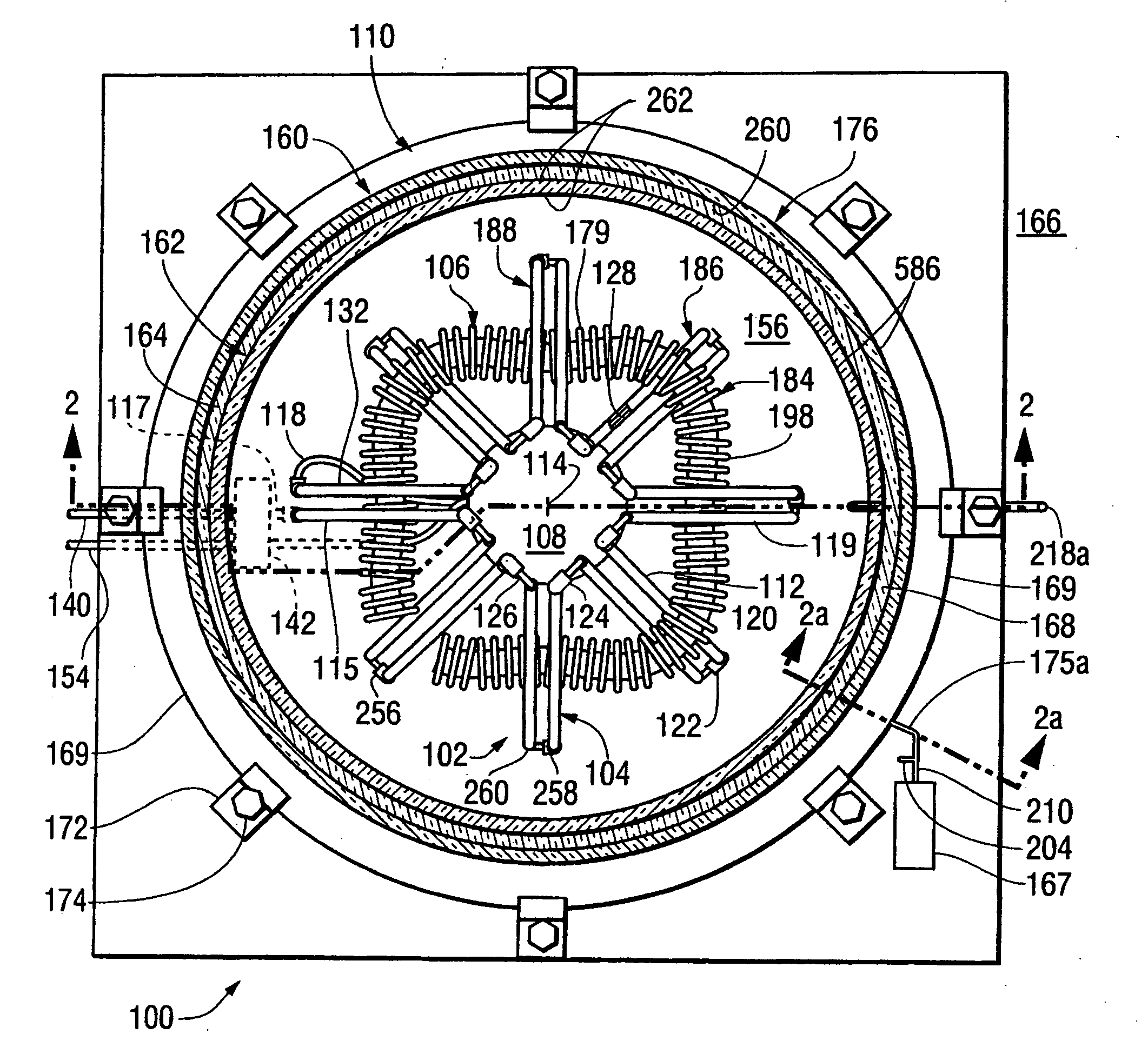
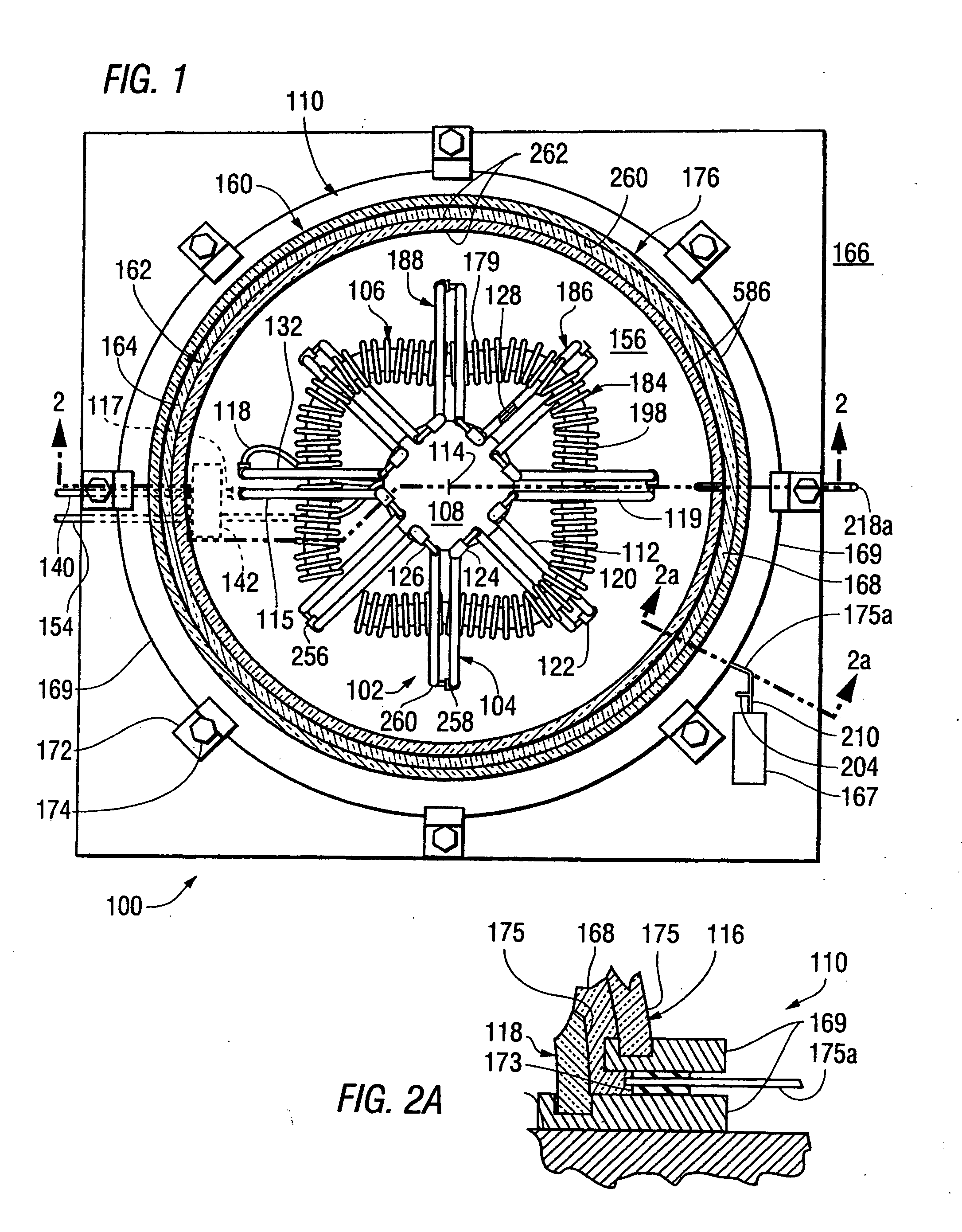
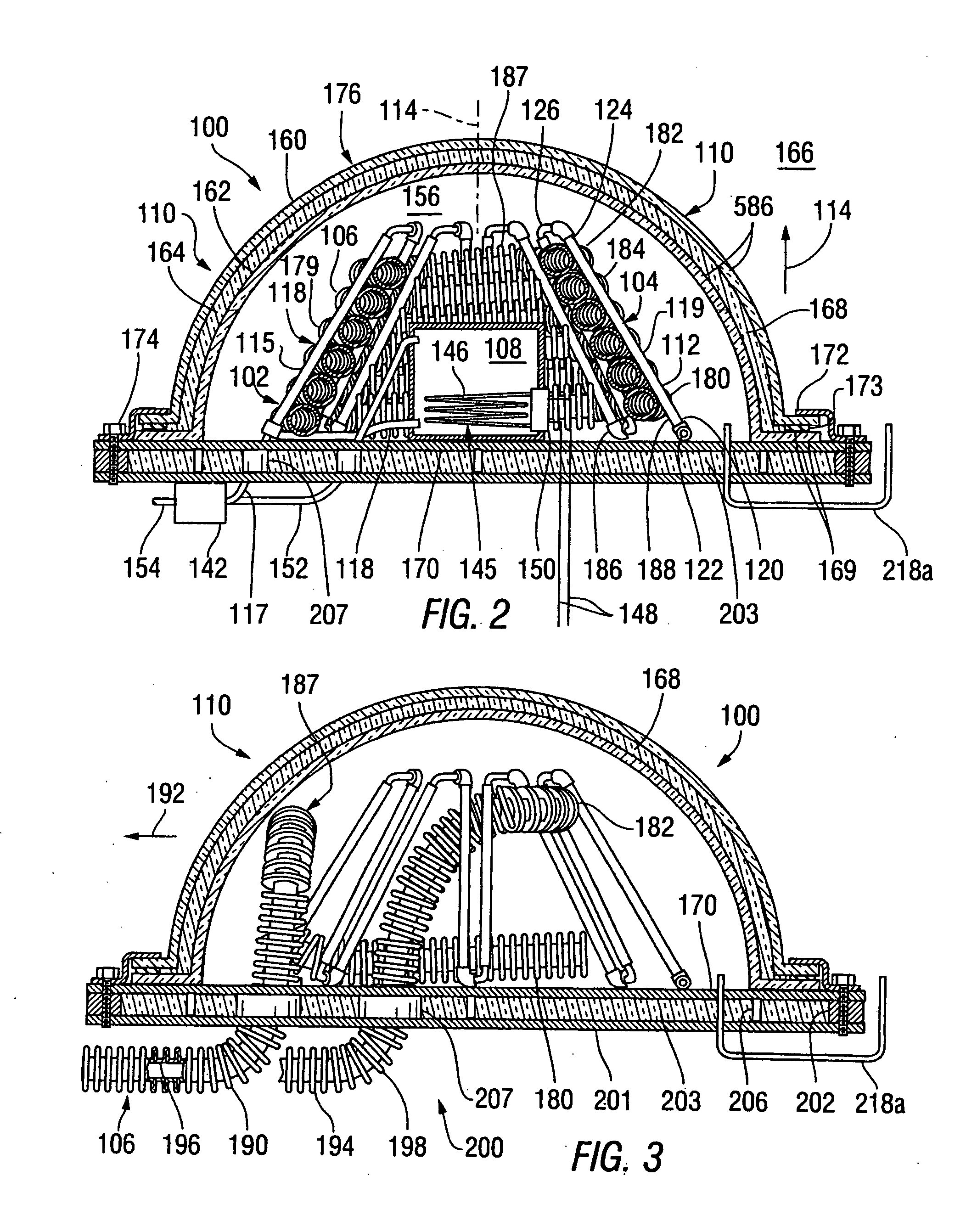
[0066]A solar heat collector having a dome-shaped structure built in accordance with the present invention will first be discussed with reference being made to FIGS. 1-7. FIG. 1 is a plan view of the solar heat collector 100, while FIG. 2 is a cross-sectional elevation thereof, taken as indicated by section lines 2-2 in FIG. 1. The solar heat collector 100 includes a frame 102 having a plurality of legs 104, a transverse hose 106 winding around the frame 102 and between the legs 104, and a reservoir 108, all held within a translucent dome structure 110.

[0067]Within the frame 102, each of the legs 104 includes a pair of tubes 112, disposed in a circular pattern 113 around a central axis 114 of the hybrid solar heat collector 100 and extending upward, in the direction of arrow 116 and inward, toward the central axis 114. The legs 104 include an inlet / outlet leg 115, in which the tubes 112 are connected to an inlet tube 117 and an intermediate tube 118, and a number of interconnected l...

second embodiment

[0083]A solar heat collector having a dome-shaped structure built in accordance with the invention will now be discussed, with reference being made to FIGS. 8-24. FIG. 8 is a perspective view of an alternative dome-shaped structure 300 extending around and over a dome-shaped solar heat collector 302, which is, for example, built as described above in reference to FIG. 5. Alternately, the dome shaped structure 300 may, for example, enclose a dome-shaped solar heat collector built as described above 1-3 and 7. The dome-shaped structure 300 includes a frame 320 having frame members 322 including horizontal frame members 324 and vertically extending frame members 326, intersecting with one another to form a plurality of frame openings 327. The dome-shaped structure 300 additionally includes base members 328 attached to the lowermost horizontal frame members 324 and to a floor structure (not shown). Fluid paths 332 into the solar heat collector 302 extend outwardly through the base membe...

third embodiment

[0109]In accordance with the invention, a thermally insulating system is provided, including at least one cavity connected to a vacuum sustaining unit and filled with an aerogel. Examples of such insulating systems will now be discussed, with reference being made to FIGS. 27-36.

[0110]FIG. 27 is a cross-sectional end elevation of a thermally insulating panel 610 built for use within a thermally insulating structure built in accordance with a third embodiment of the invention to include a plurality of such insulating panels 610 attached to a vacuum sustaining unit 167, as described above in reference to FIG. 4A. The insulating panel 610 includes a pair of side panels 612 held in a spaced-apart condition within a frame 614. An evacuation tube 616 extends through the frame to provide for the evacuation of air from the interior space 618 between the side panels 612, and seals 620 prevent, or at least minimize, the return of air into the interior space 618 following evacuation. In the exa...


PUM


Abstract

A thermal insulation system includes an evacuated structure having an internal space filled with an aerogel layer, in which a vacuum is sustained by a vacuum pump operating when it is determined that a pressure within the internal space has risen to a predetermined level. For example, such a system is used within a dome structure extending over and around a heat receiving structure within a solar heating system or within a system providing thermal insulation for a building structure, a refrigerator, or a railroad car.

Description

RELATED APPLICATIONS[0001]This is a continuation-in-part of a copending U.S. patent application Ser. No. 12 / 592,085, filed Nov. 19, 2009. This application claims the benefit of a prior-filed U.S. Provisional Patent Application No. 61 / 395,886, filed May 18, 2010 and of U.S. Provisional Patent Application No. 61 / 463,703, filed Feb. 22, 2011.FEDERALLY SPONSORED RESEARCH OR DEVELOPMENT[0002]Not ApplicableBACKGROUND OF THE INVENTION[0003]1. Field of the Invention[0004]This invention relates to thermal insulation systems, more particularly to such systems including evacuated structures, and yet more particularly to the use of such systems to allow heat retention within solar heat collectors, and to the use of such systems to prevent a transfer of heat into or away from an interior space.[0005]2. Summary of the Background Information[0006]A solar heat collector typically includes a heat receiving structure through which a fluid, such as water, is circulated to be heated by solar radiation....

Claims


Application Information

Patent Timeline
Patent Type & Authority Applications(United States)
IPC IPC(8): F24J2/51
CPCF16L59/065F24J2/0488F24J2/08F24J2/26Y02E10/40F24J2/507F24J2/515Y02B10/22F24J2/505F24S80/52F24S80/65F24S70/60F24S10/75F24S80/54F24S23/30F24S80/56F24S80/58Y02B10/20
Inventor FLAHERTY, MICHAEL
Owner FLAHERTY MICHAEL
Why Eureka
Try Eureka