Hybrid drive device

a hybrid drive and drive shaft technology, applied in the direction of electric propulsion mounting, transportation and packaging, gearing, etc., can solve the problems of reducing the comfort of the occupants, difficult to ensure a sufficient amount of torque of the second rotating electrical machine for moving the vehicle rearward, and difficult to ensure a sufficient range with a limited amount of electric power, so as to achieve the effect of reducing the manufacturing cost of the hybrid drive devi

Inactive Publication Date: 2011-09-15
AISIN AW CO LTD
View PDF0 Cites 27 Cited by
  • Summary
  • Abstract
  • Description
  • Claims
  • Application Information

AI Technical Summary

Benefits of technology

[0008]Accordingly, it is desired to implement hybrid drive devices capable of easily switching modes, and also capable of reducing vibrations and ensuring a sufficient range and a sufficient driving force even when the vehicle travels rearward.
[0036]According to this structure, the manufacturing cost of the hybrid drive device can be reduced by using a general-purpose part such as the friction engagement brake that is operated by a fluid pressure or an electromagnetic force.

Problems solved by technology

Thus, depending on the traveling state of the vehicle such as a low vehicle speed state, and the external environmental conditions such as extremely low temperature conditions, vibrations of the engine which are transmitted to the input member may further be transmitted to the output member, which may reduce the comfort of the occupants.
Thus, vibrations of the engine are hardly transmitted to the output member, but it is difficult to ensure a sufficient range with a limited amount of electric power that is stored in an electric power storage device such as a battery.
Moreover, depending on the external environmental conditions such as extremely low temperature conditions, it may be difficult to ensure a sufficient amount of torque of the second rotating electrical machine for moving the vehicle rearward.

Method used


Image

  • Hybrid drive device
  • Hybrid drive device
  • Hybrid drive device

Examples


first embodiment

1. First Embodiment

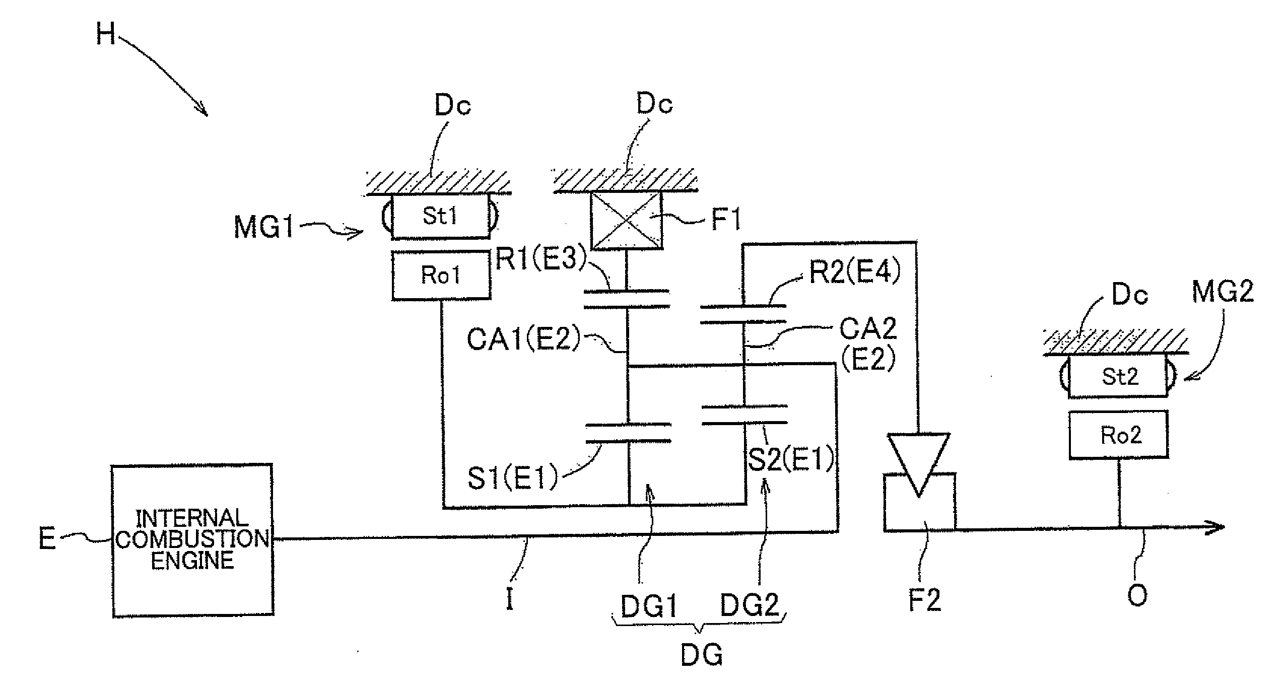
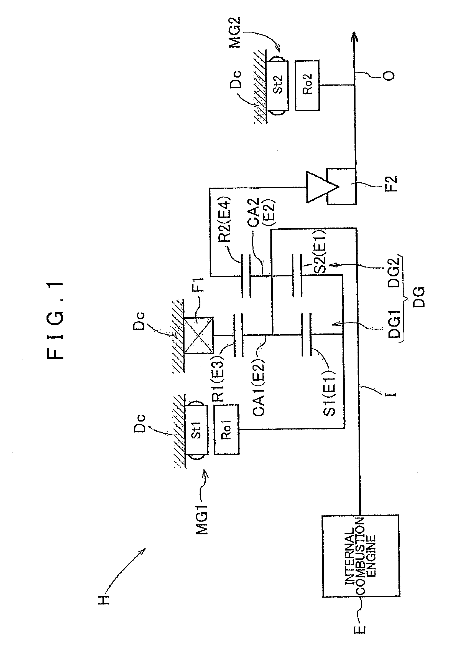
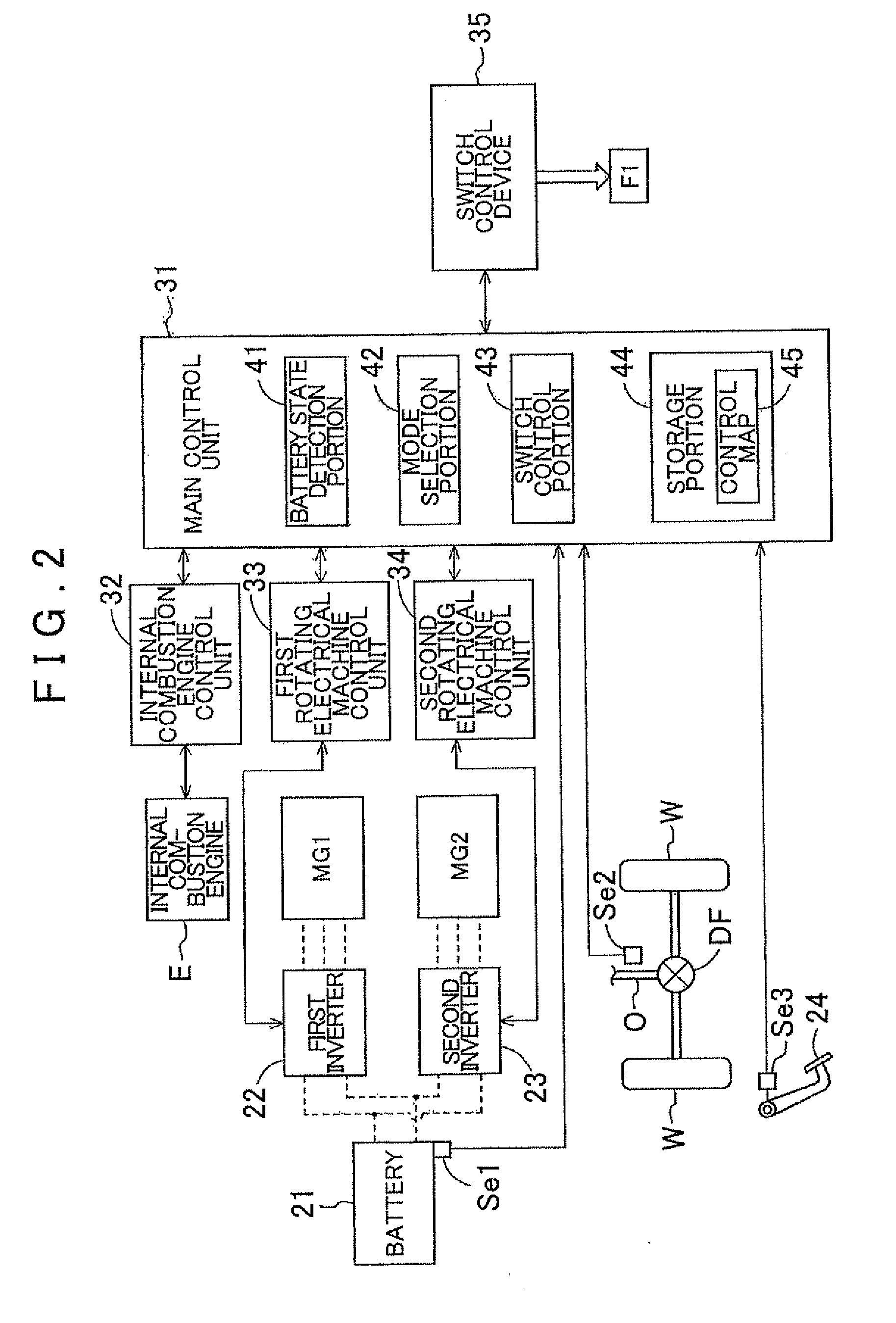
[0052]A first embodiment of the present invention will be described below with reference to the accompanying drawings. FIG. 1 is a skeleton diagram showing a mechanical structure of a hybrid drive device H according to the present embodiment. Note that the lower half structure that is symmetrical with respect to the central axis is not shown in FIG. 1. FIG. 2 is a schematic diagram showing a system configuration of the hybrid drive device H according to the present embodiment. Note that in FIG. 2, solid arrows represent transmission paths of various information, broken lines represent transmission paths of electric power, and an outline arrow represents a transmission path of motive power.

[0053]As shown in FIG. 1, the hybrid drive device H includes: an input shaft I drivingly coupled to an internal combustion engine E; a first rotating electrical machine MG1; a second rotating electrical machine MG2; an output shaft O drivingly coupled to wheels W (see FIG. 2) and...

second embodiment

2. Second Embodiment

[0121]A second embodiment of the present invention will be described below with reference to the accompanying drawings. FIG. 12 is a skeleton diagram showing a mechanical structure of a hybrid drive device H of the present embodiment. Note that as in FIG. 1, the lower half structure that is symmetrical with respect to the central axis is omitted in FIG. 12. The mechanical structure of the hybrid drive device H of the present embodiment is partly different from the first embodiment in that another one-way clutch (a second one-way clutch F3) is added to the structure of the hybrid drive device H of the first embodiment. Since the second one-way clutch F3 is added, the hybrid drive device H of the present embodiment is partly different from that of the first embodiment in that the hybrid drive device H of the second embodiment further includes a second electric travel mode as a switchable mode. The hybrid drive device H of the present embodiment will be described in...


PUM


Abstract

A hybrid drive device configured with an input member coupled to an internal combustion engine, a first rotating electrical machine, a second rotating electrical machine, an output member drivingly coupled to wheels and the second rotating electrical machine; and a differential gear unit. A first rotating element of the differential gear unit is drivingly coupled to the first rotating electrical machine. A second rotating element is drivingly coupled to the input member. A third rotating element is selectively fixed to a non-rotating member by a rotating restricting device. A fourth rotating element is selectively drivingly coupled to the output member via a rotational direction restricting device. Accordingly, the rotational direction restricting device is provided so as to allow the output member to rotate only in a positive direction relative to the fourth rotating element of the differential gear unit.

Description

INCORPORATION BY REFERENCE[0001]The disclosure of Japanese Patent Application No. 2010-051866 filed on Mar. 9, 2010 including the specification, drawings and abstract is incorporated herein by reference in its entirety.BACKGROUND OF THE INVENTION[0002]The present invention relates to hybrid drive devices including an input member drivingly coupled to an internal combustion engine, a first rotating electrical machine, a second rotating electrical machine, an output member drivingly coupled to wheels and the second rotating electrical machine, and a differential gear unit.DESCRIPTION OF THE RELATED ART[0003]For example, a device described in Japanese Patent Application Publication No. JP-A-2002-316542 is known as a hybrid drive device including an input member drivingly coupled to an internal combustion engine, a first rotating electrical machine, a second rotating electrical machine, an output member drivingly coupled to wheels and the second rotating electrical machine, and a differ...

Claims


Application Information

Patent Timeline
Patent Type & Authority Applications(United States)
IPC IPC(8): B60K6/50B60K6/42B60K6/46B60K6/38B60L50/16
CPCB60K1/02Y02T10/70B60K6/383B60K6/445B60K6/46F16H3/52F16H3/728F16H2037/0866F16H2037/0873F16H2200/2007Y02T10/6217Y02T10/6239B60L11/14Y02T10/7077B60K6/365B60K6/48B60K2006/4833B60L50/16Y02T10/62Y02T10/7072
Inventor ANDO, MASAHIKO
Owner AISIN AW CO LTD
Why Eureka
Try Eureka