
Portable solar and wind-powered energy generating system

a solar and wind-powered energy generating system technology, applied in the direction of wind motors with solar radiation, electric generator control, greenhouse gas reduction, etc., can solve the problems of battery charging capacity, the ability to recharge the storage cell or battery remains a major drawback to acceptance by the general populace, and the demand for electrical power continues to increase unabated

Active Publication Date: 2011-09-15
MILLER LYNN A
View PDF13 Cites 67 Cited by
  • Summary
  • Abstract
  • Description
  • Claims
  • Application Information

AI Technical Summary

Benefits of technology

[0022]These and other features of the present invention will become readil

Problems solved by technology

The initial limitation on an electric vehicle was the charging capacity of the batteries, so as to allow the vehicle to operate at comparable speeds with internal combustion engines and over comparable time periods.
Technological advances in storage cell design have made electric vehicles a viable alternative to internal combustion engines; however, the ability to recharge the storage cell or batteries remains a major drawback to acceptance by the general populace.
Electricity, however, is typically provided through the conventional electrical grid, and power plants generate electricity through the burning of fossil fuels or through the usage of potentially hazardous nuclear power systems.
As time goes on, the demand for electrical power continues to increase unabated.
Unfortunately, large-scale solar collectors and generators, along with wind farms, presently have numerous disadvantages for providing power to the general public, as opposed to single-family homes, for example.
Solar modules, consisting of at least one solar panel, and wind turbines are very expensive and must also be located in areas of high sun exposure and wind potential.
As a result, the development time is long and costs are very high.
Because of these restrictions, many new solar and big wind farms cannot be built for six to ten years.
The transmission of such generated electric power over long distances has taxed the existing transmission grid to its limits, thereby adding to the nation's already most pressing energy and electric power problems, including blackouts and brownouts, energy security concerns, power quality issues, tighter emissions standards, transmission bottlenecks, and the desire for greater control over energy costs.
These transmission grid problems have constrained the development of solar and wind farms until either developers or governmental entities build new transmission capacity over long distances.
This will require both huge capital investment and very long development cycles because of the need to purchase additional “rights-of-way” or easements for the new transmission lines.
Such delays and capital investment substantially increase the per KWH costs of energy to the consumer, thereby making solar and wind generated electric power more expensive.
However, typical wind driven turbines are relatively inefficient, often only converting a small fraction of the wind's kinetic energy into usable electrical power, and also only being effective when the wind is blowing in one particular direction within a small range of desirable speeds.
Similarly, small-scale solar generation is well known, but typically is limited to only a small-scale and fixed location, such a single-family home or the like.
Presently, neither solar nor wind power are readily available for usage on a public scale, such as that required to provide public charging stations for electrical vehicles.

Method used


Image

  • Portable solar and wind-powered energy generating system
  • Portable solar and wind-powered energy generating system
  • Portable solar and wind-powered energy generating system

Examples


Embodiment Construction

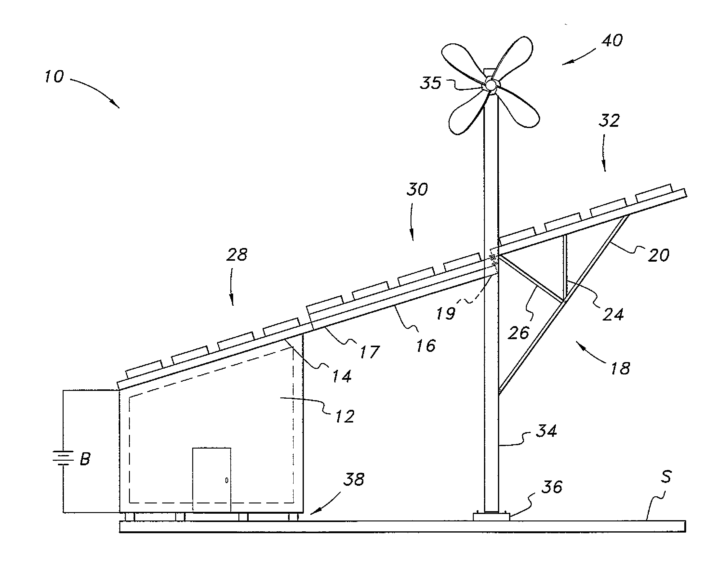
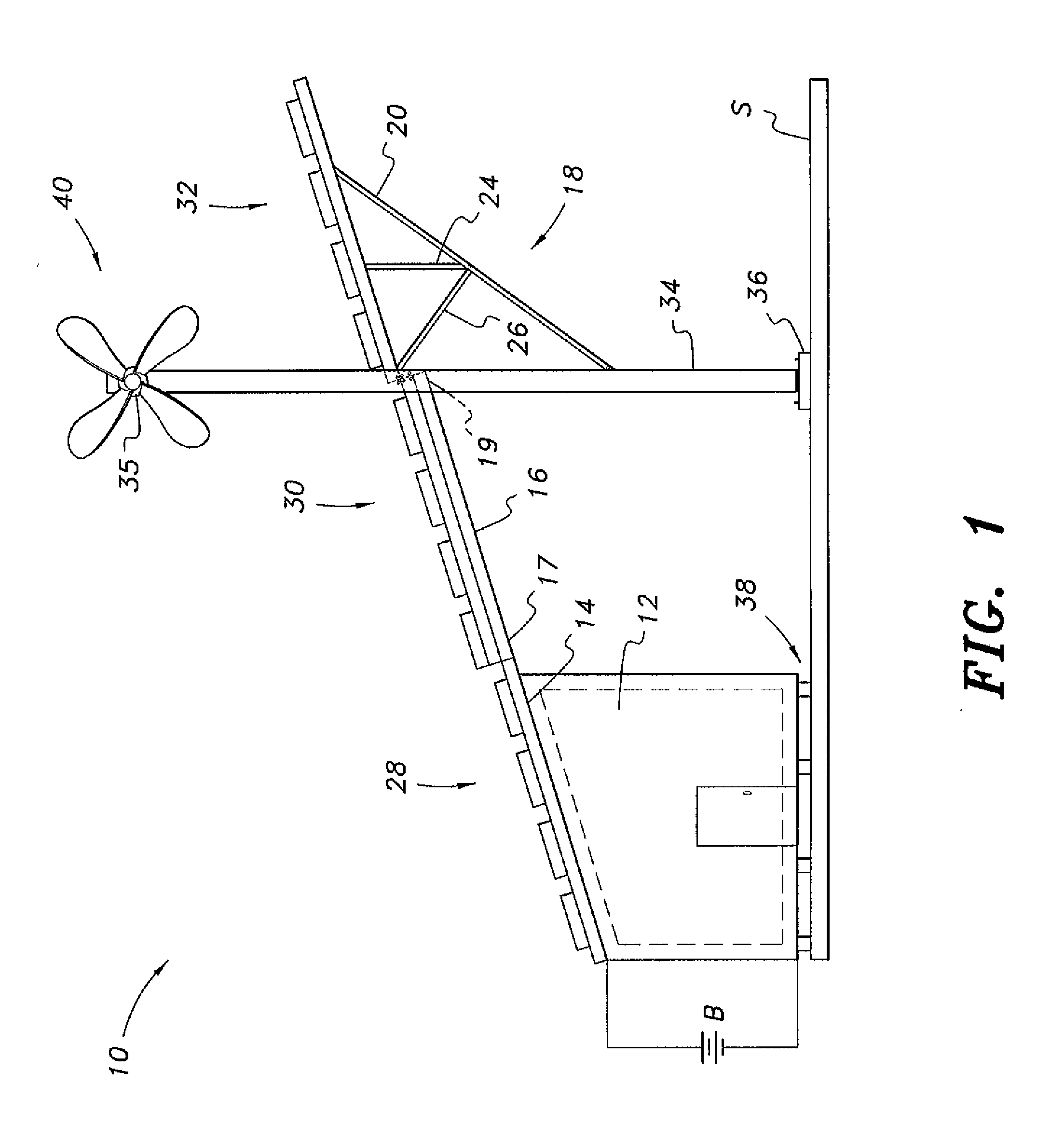
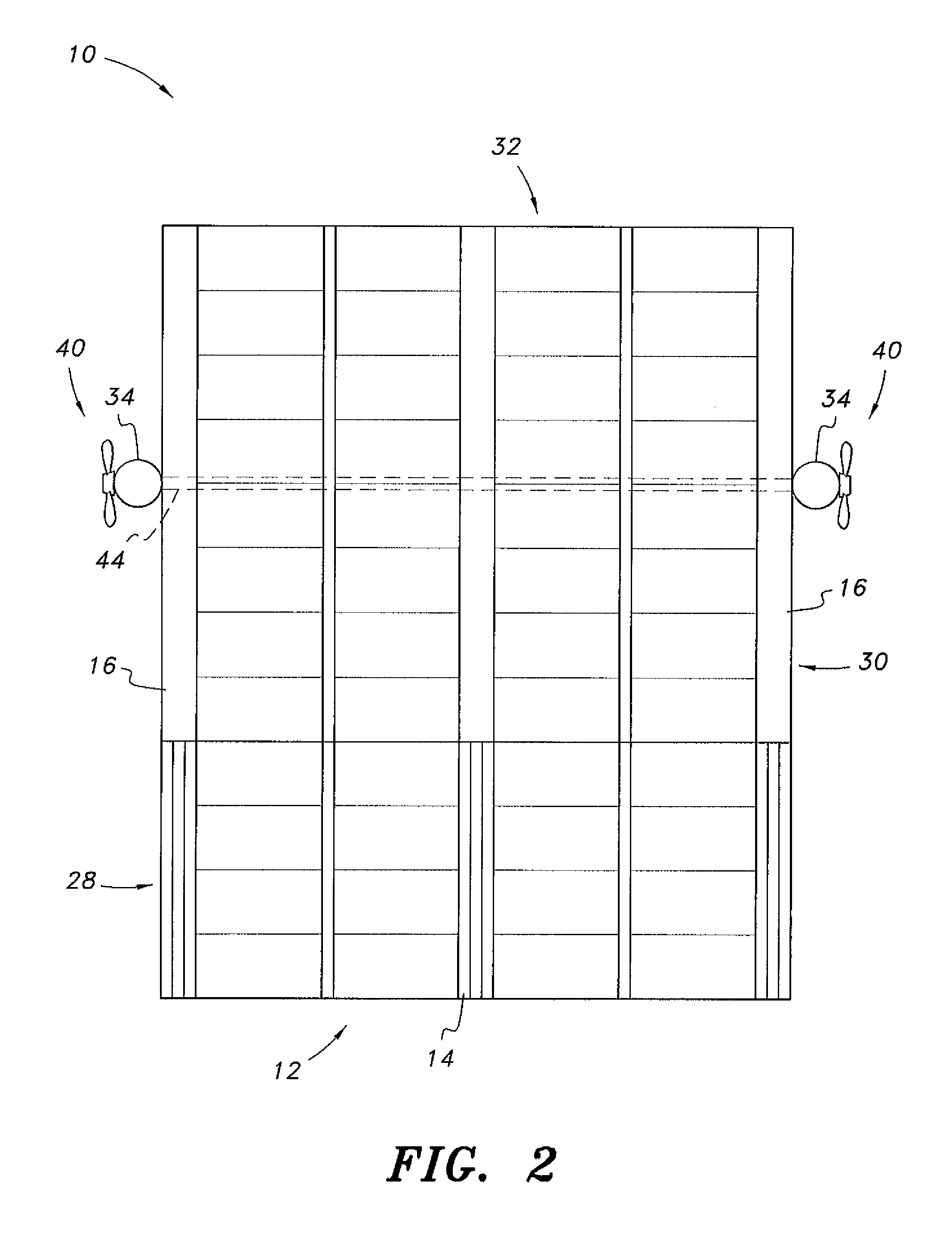
[0034]FIG. 1 illustrates a first embodiment of the portable solar and wind-powered energy generating system 10. The system 10 is an ecologically friendly, portable station for generating electricity. The portable solar and wind-powered energy generating system 10 may be used as a portable charging station for electrically driven vehicles, for example. It should be understood that the electrical power may be used for any desired purpose, such delivery to an electrical load, such as a storage battery, a power outlet, a charger for electrical vehicles or the like, or a combination thereof. Alternatively, the electrical energy may be transmitted into the pre-existing electrical power grid. Further, the power outlet, storage battery or other electrical load may be associated with a portable office, work site, portable educational facility or other venue.

[0035]As best shown in FIGS. 1 and 2, the portable solar and wind-powered energy generating system 10 includes a portable enclosure 12 h...


PUM


Abstract

The portable solar and wind-powered energy generating system provides an ecologically friendly, portable system for generating electricity. The system includes a portable enclosure having a roof, along with first and second solar modules. The first solar module is mounted on the roof of the portable enclosure. A portable vertical support is removably positioned adjacent the portable enclosure. A wind turbine is preferably mounted on an upper end thereof. An extensible support releasably extends between the roof and the vertical support for releasably supporting the second solar module. Preferably, a third solar module is further provided, and a collapsible support is mounted on the portable vertical support for releasably supporting the third solar module. The wind turbine is in electrical communication with the first, second and third solar modules, and generated electricity is delivered to an electrical load, such as a storage battery, a charger for electrical vehicles, or the like.

Description

CROSS-REFERENCE TO RELATED APPLICATION[0001]This application claims the benefit of U.S. Provisional Patent Application Ser. No. 61 / 282,656, filed Mar. 12, 2010.BACKGROUND OF THE INVENTION[0002]1. Field of the Invention[0003]The present invention relates to electrical generation, and particularly to a portable solar and wind-powered energy generating system that provides an ecologically friendly, portable system for generating electricity for to be delivered to an electrical load, such as a storage battery, a power outlet, a charger for electrical vehicles or the like, or a combination thereof, or, alternatively, the electrical energy may be transmitted into the pre-existing electrical power grid.[0004]2. Description of the Related Art[0005]Concerns over rising pollution, global warming and the cost of fuel have led to a greater interest in the use of electric power for powering vehicles, either using electric power alone, or electric power in a hybrid vehicle, which also includes a ...

Claims


Application Information

Patent Timeline
IPC IPC(8): F03D9/00H01L31/042
CPCF03D9/007F03D9/021H02S10/10H02S30/20Y02E10/725F03D9/11F03D9/25F03D13/20H02S10/12H02S10/40H02S20/30Y02E10/50Y02E10/72Y02E10/728Y02E70/30
Inventor MILLER, LYNN A.
Owner MILLER LYNN A
Learn More