Buoyancy Energy Cell

a technology of buoyancy energy and energy cell, which is applied in the direction of electric generator control, machines/engines, mechanical equipment, etc., can solve the problems of generating little or no electricity, and not disclosing the electrical generator directly mounted on the float, etc., to achieve high-efficiency energy or electricity generation and energy generation

Inactive Publication Date: 2011-09-15
RYAN JAMES
View PDF8 Cites 12 Cited by
  • Summary
  • Abstract
  • Description
  • Claims
  • Application Information

AI Technical Summary

Benefits of technology

[0013]A device for the storage and generation of energy, and in particular electrical energy includes a cell or chamber which moves upwardly and downwardly in a body of water. Cog wheels are connected to the cell. The cog wheels are connected to the shafts of generators. Rotation of the cog wheels operates the generators which produce energy. The cog wheels engage anchor chains or vertical supports. One end of each anchor chain is secured to an anchor located at the bottom of the body of water. The other end of the anchor chain is secured to a float which floats at or near the surface of the body of water. The up and down movement of the cell causes the cog wheels to move upwardly and downwardly along the anchor chains and thereby rotate. This rotation drives the energy generator and generates energy, preferably electricity. The cog wheels are permitted to rotate upon the receipt of a request for energy. This results in a highly efficient source of energy or electricity.

Problems solved by technology

While this patent teaches employing air and water to raise and lower a float which can be used to generate electricity, it does not disclose the electrical generators directly mounted on the float.
Furthermore, it will generate little or no electricity when the seas are calm.
While this patent teaches employing air and water to raise and lower a float which can be used to generate electricity, it does not disclose the electrical generators directly mounted on the float.
Further, it does not disclose the use of water pumps to empty the floating bodies.
Also, pumping air into a submerged vessel is far less efficient, from an energy standpoint, than pumping water out of the same vessel.
While this patent teaches employing air and water to raise and lower a float which can be used to generate electricity, it does not disclose the electrical generators directly mounted on the float nor the use of water pumps to empty the float.
Also, this patent does not demonstrate a practical means of pressurizing the fluid nor disclose how such pressurized fluid is drained from the submerged container.
However, there is no disclosure of generation of electricity.
This device does not utilize air to change the buoyancy of a tank or float.

Method used


Image

  • Buoyancy Energy Cell
  • Buoyancy Energy Cell
  • Buoyancy Energy Cell

Examples


Embodiment Construction

[0025]While the present invention is susceptible of embodiment in various forms, there is shown in the drawings and will hereinafter be described a presently preferred, albeit not limiting, embodiment with the understanding that the present disclosure is to be considered an exemplification of the present invention and is not intended to limit the invention to the specific embodiments illustrated.

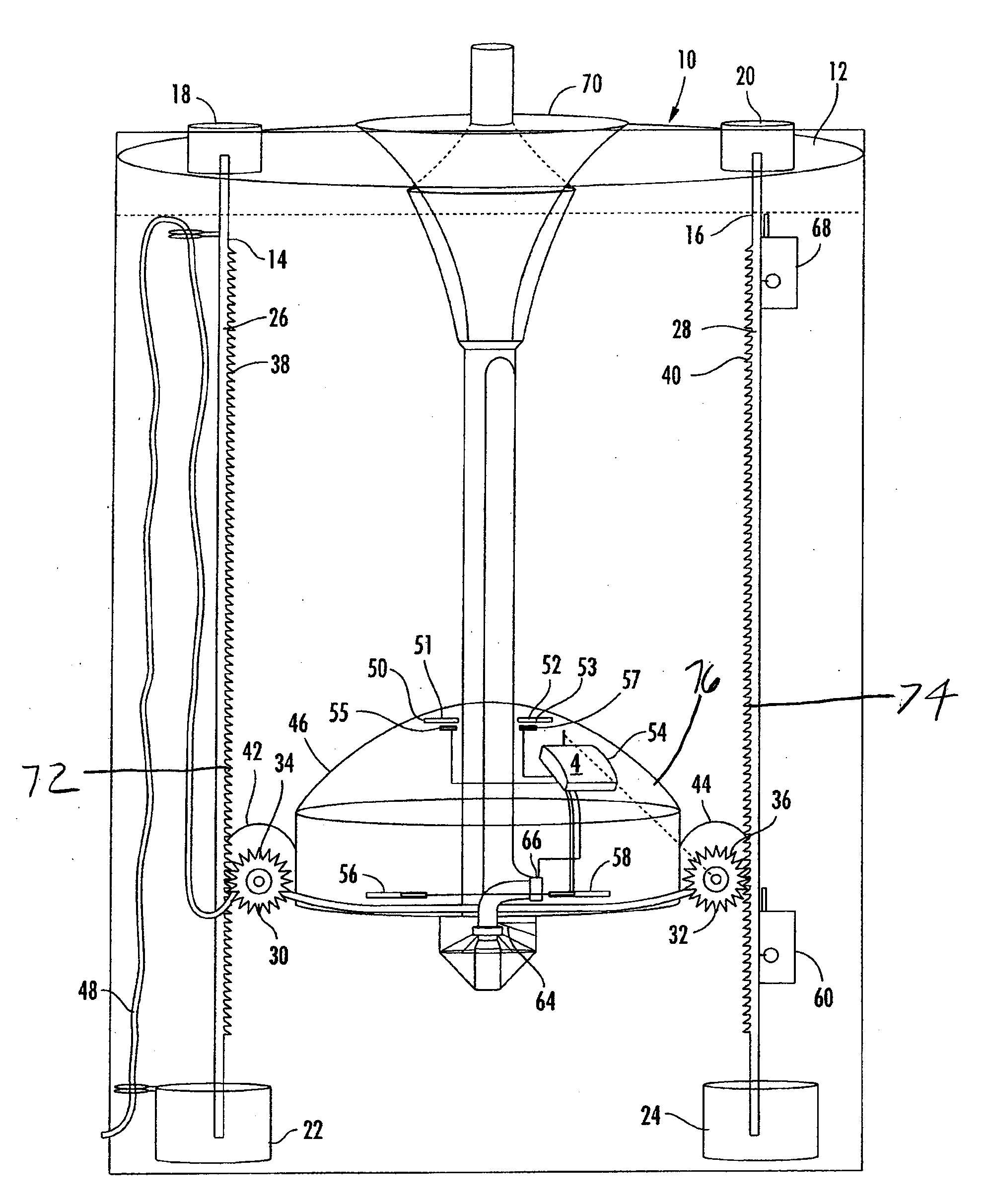
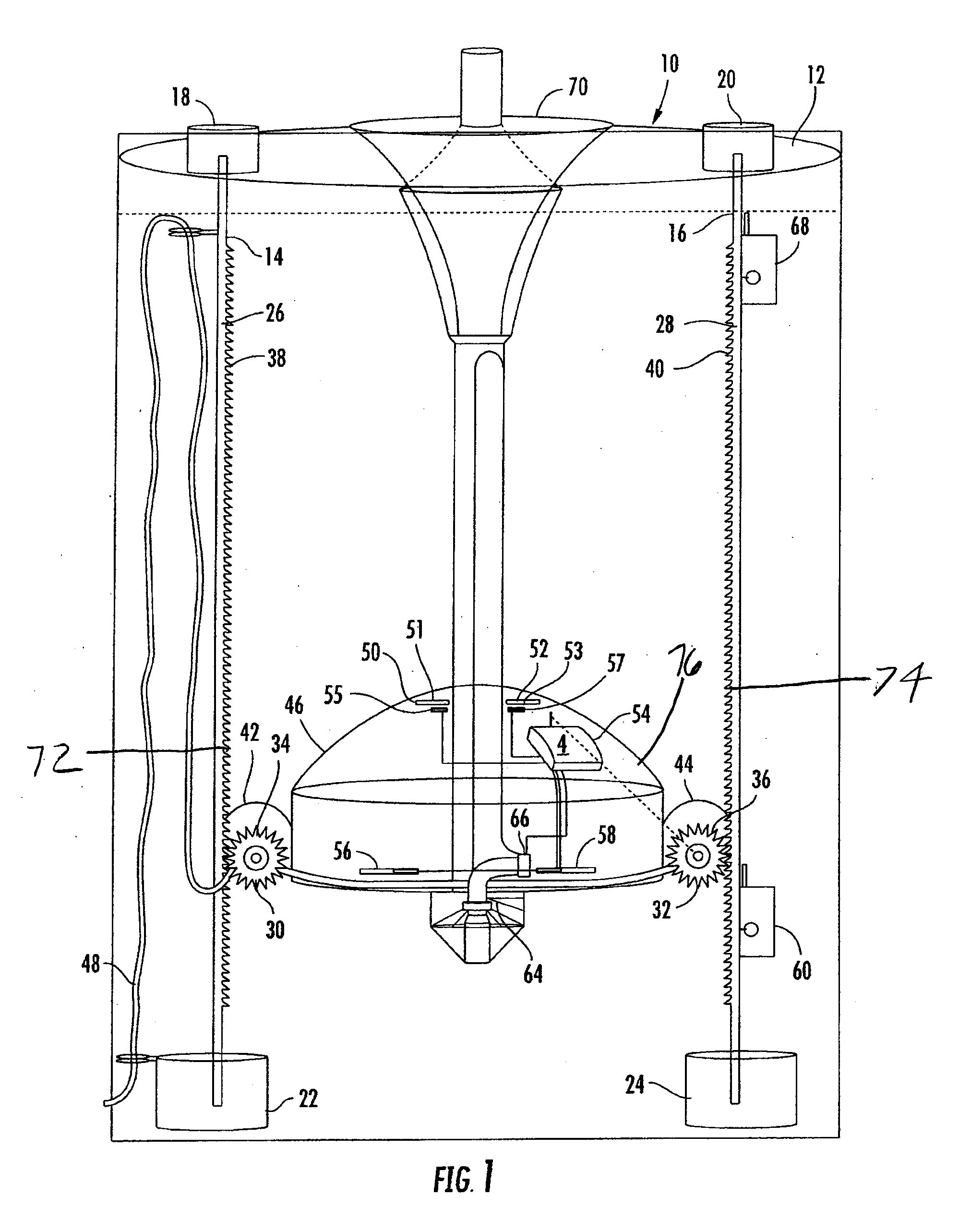
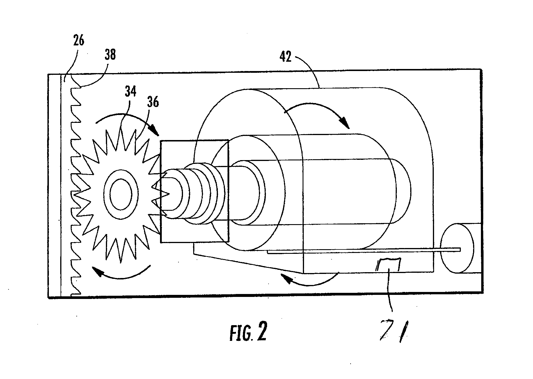
[0026]A first preferred embodiment of the present invention is illustrated in FIGS. 1-2. In this embodiment an energy producing cell 10 is located within a body of water 12. The body of water may be a tank, a lake, a pond, an ocean, a river, etc. It can be a natural body of water or a man-made body of water. Two anchoring chains or vertical guides 14 and 16 are vertically positioned within the body of water 12. While two anchor chains are illustrated, any number of anchor chains or vertical guides 14, 16 can be employed. Floats, buoys or upper supports 18 and 20 are secured to one end of the...


PUM


Abstract

A device for the generation of energy and in particular electrical energy includes a cell or chamber which moves upwardly and downwardly in a body of water. Cog wheels are connected to the cell. The cog wheels are connected to the shafts of generators. Rotation of the cog wheels operates the generators which produce energy. The cog wheels engage anchor chains or vertical supports. The up and down movement of the cell causes the cog wheels to move upwardly and downwardly along the anchor chains and thereby rotate. This rotation drives the energy generator and generates energy, preferably electricity. The cog wheels are permitted to rotate upon the receipt of a request for energy. This results in a highly efficient source of energy or electricity. Energy from other sources, such as wind or tides, can be utilized to operate the cell.

Description

CROSS REFERENCE TO RELATED APPLICATIONS[0001]This application is a continuation-in-part of U.S. patent application Ser. No. 12 / 463,193, filed May 8, 2009, entitled “BUOYANCY ENERGY CELL,” the entirety of which is incorporated herein by reference.FIELD OF THE INVENTION[0002]The present invention relates to energy generation, and more particularly to electrical power generation devices or equipment. The electrical generation device includes a container or tank positioned within a body of water. Water is introduced into and evacuated from the container or tank, resulting in the container floating or sinking in the body of water. The upward and downward movement of the container operates equipment which in turn generates electrical power.BACKGROUND OF THE INVENTION[0003]Electrical power generation utilizing hydraulic equipment, thermal equipment and nuclear equipment has been known for many years. The use of thermal equipment, such as coal-fired, oil-fired and natural gas-fired power pl...

Claims


Application Information

Patent Timeline
Patent Type & Authority Applications(United States)
IPC IPC(8): H02K7/18H02P9/04
CPCF03B17/02Y02E10/20F03B17/04
Inventor RYAN, JAMES
Owner RYAN JAMES
Why Eureka
Try Eureka