Illumination system for illuminating a display device, and display device

a technology of illumination system and display device, which is applied in the direction of instruments, lighting and heating apparatus, optical elements, etc., can solve the problems of unsuitable segmentation and too sharp boundary, and achieve uniform (homogeneous) illumination, avoid visible artefacts, and the effect of thickness of illumination system

Inactive Publication Date: 2011-09-15
KONINKLIJKE PHILIPS ELECTRONICS NV
View PDF13 Cites 10 Cited by
  • Summary
  • Abstract
  • Description
  • Claims
  • Application Information

AI Technical Summary

Benefits of technology

[0005]This object can be achieved by providing an illumination system according to the preamble, comprising: multiple translucent tiles, each translucent tile being provided with reflecting means for reflecting light towards an outcoupling surface of the tile, and multiple arrays of one or multiple light emitting diodes (LEDs), each array of LEDs being arranged to emit light substantially directed towards at least one translucent tile, the reflecting means being adapted to reflect light towards at least one outcoupling surface of the tile facing a light receiving surface positioned at a distance from the tiles, said reflection being such that light emitted by at least two tiles is mixed at least partially before being received by said light receiving surface. By applying multiple translucent tiles (or translucent segments), a dimmable illumination system can be realised, wherein the tiles can be selectively (partial dimming) and even integrally (total dimming) switched on and off depending on the image content. Since light emitted by one or multiple tiles is mixed at least partially with light emitted by at least one other tile in the space between the tiles and the light receiving surface, a relatively uniform (homogeneous) illumination of the light receiving surface and hence of a display device to be illuminated can be realised. In addition, partial mixing between tiles leads to smooth light distributions on a non-emissive display device, which is favourable for avoiding visible artefacts. The light receiving surface is commonly substantially flat, and is preferably formed by an optical redirection structure which may be part of the illumination system and / or of the display device to be illuminated. The optical redirection structure is adapted to redirect light emitted by the tiles in the direction of a display device to be illuminated to secure a proper and uniform illumination of said display device. The optical redirection structure may be adapted either to redirect received light in a predefined direction or to redirect light in a more diffuse (random) direction towards the display device to be illuminated. To allow mixing in the space between the tiles and the redirection structure, an angular emission of light emitted by the tiles will commonly be beneficial, wherein preferably at least a substantial part of the light emitted by the tiles is emitted in a direction enclosing an angle of at least 45 degrees with a normal to the light receiving surface, in particular the redirection structure. Hence, it is beneficial that the tiles are adapted to emit light in a direction enclosing an angle with a receiving surface of the optical redirection structure. Due to this angular distribution of light, the thickness of the space between the tiles and the redirection structure, and hence the thickness of the illumination system as such, can be reduced significantly compared to the thickness of known illumination systems. It has been shown that the thickness of the space between the tiles and the redirection structure can be reduced to several millimetres. Commonly, it is also advantageous that each tile is adapted to emit light in a direction enclosing an angle of between 0 and 90 degrees with a normal to an outcoupling surface of said tile. In this manner the length of the transport path of the light between the tiles and the redirection structure can be further increased, which may result in a (further) reduction of the thickness of the space between the tiles and the redirection structure. Beside conventional LEDs also Organic LEDs (OLEDs) may be used in the illumination system according to the invention. Application of OLEDs could be interesting, since the application of OLEDs provides an increased degree of freedom of design of the illumination system according to the invention. Herein, it is conceivable to apply OLED strips or other elongated OLEDs to illuminate the tiles.

Problems solved by technology

The application of a conventional light guide design makes the boundary too sharp and not suitable to act as a segment or tile in a dimmable backlight application.

Method used


Image

  • Illumination system for illuminating a display device, and display device
  • Illumination system for illuminating a display device, and display device
  • Illumination system for illuminating a display device, and display device

Examples


Embodiment Construction

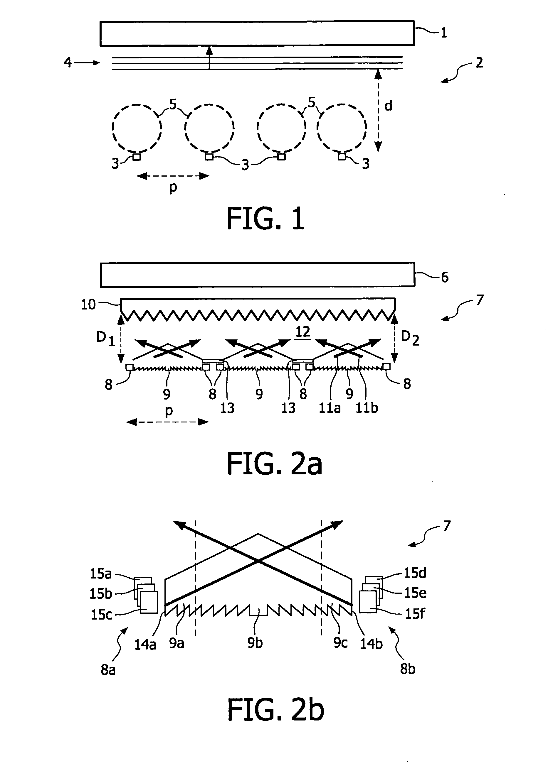
[0020]FIG. 1 shows a side view of a display device 1, such as an LCD, comprising an illumination system 2 known from the prior art. The known illumination system 2 comprises multiple LEDs 3 being positioned equidistantly from a stack of optical foils 4. Light 5 emitted by the LEDs 3 and received by the stack of optical foils 4 will partially be redirected as shown in the direction of the display device 1 and partially be reflected back towards the LEDs 3. The LEDs 3 can be selectively switched on and off, which enables dimming of the illumination system 2. To achieve a relatively uniform illumination of the display device 1, the LEDs 3 are positioned at a minimum distance d from the stack of optical foils 4, wherein d is at least approximately equal to or larger than the mutual distance p (pitch) between the LEDs 3, as a result of which the known illumination system 2 is relatively voluminous. Commonly the distance d (and the pitch p) will be between 2 and 5 cm.

[0021]FIG. 2a shows a...


PUM


Abstract

Display devices are used in portable computer systems, imaging systems, and other electronic devices. Many of these display devices require a source of light to illuminate a display screen. The invention relates to an illumination system for illuminating said display devices. The invention also relates to a display device provided with such an illumination system.

Description

FIELD OF THE INVENTION[0001]The invention relates to an illumination system for illuminating display devices. The invention also relates to a display device provided with such an illumination system.BACKGROUND OF THE INVENTION[0002]Display devices are used in portable computer systems, imaging systems, and other electronic devices. Many of these display devices require a source of light to illuminate a display screen. One example of a non-emissive display device that requires an external source of light is a liquid crystal display (“LCD”). LCDs typically include a liquid crystal layer containing liquid crystals which operate as light valves, allowing transmission of light in one state and blocking transmission of light in a second state. Placing a source of light or backlight behind the liquid crystal display and electronically controlling the switching of the light valves allows a user to view the front of the LCD to read text or images formed by the switched light valves. LCDs hav...

Claims


Application Information

Patent Timeline
Patent Type & Authority Applications(United States)
IPC IPC(8): H05B37/02F21V7/00
CPCG02B6/0038G02B6/0046G02B6/0055G02F1/133621G02F1/133603G02F1/133606G02B6/0078
Inventor CORNELISSEN, HUGO JOHANPIJLMAN, FETZECHEN, CHUN-HO
Owner KONINKLIJKE PHILIPS ELECTRONICS NV
Why Eureka
Try Eureka