Method and Apparatus for Supervisory Circuit for Ground Fault Circuit Interrupt Device

a fault circuit and interrupt device technology, applied in testing circuits, emergency protective arrangements for limiting excess voltage/current, instruments, etc., can solve problems such as short circuit, electric shock, current leakage, etc., and achieve the effect of simplifying the assembly of the gfci device and reducing the amplitude of test curren

Active Publication Date: 2011-09-15
SIEMENS IND INC
View PDF11 Cites 34 Cited by
  • Summary
  • Abstract
  • Description
  • Claims
  • Application Information

AI Technical Summary

Benefits of technology

[0007]The present invention provides an apparatus and method for a supervisory circuit in a ground fault detection device, such as a ground fault circuit interrupt (GFCI) device. Embodiments of the present invention utilize a stimulus on a second winding added to a differential current transformer for a self test of a GFCI device. This reduces the amplitude of the test current needed to test the GFCI device and simplifies assembly of the GFCI device.

Problems solved by technology

Current leakage occurs when current flowing through a line, or “hot” conductor, from a source load is diverted to ground without returning to the source.
This leakage may result from an accidental short circuit, such as from a defective load attached to the line.
If a person touches the load, the leakage current may pass through the person's body to ground, leading to an electric shock.
A difference in current levels implies that some current has leaked from the circuit and a ground fault exists.
This current imbalance will produce uncanceled flux in the differential transformer's core, resulting in an output from the multi-turn secondary winding.

Method used


Image

  • Method and Apparatus for Supervisory Circuit for Ground Fault Circuit Interrupt Device
  • Method and Apparatus for Supervisory Circuit for Ground Fault Circuit Interrupt Device
  • Method and Apparatus for Supervisory Circuit for Ground Fault Circuit Interrupt Device

Examples


Embodiment Construction

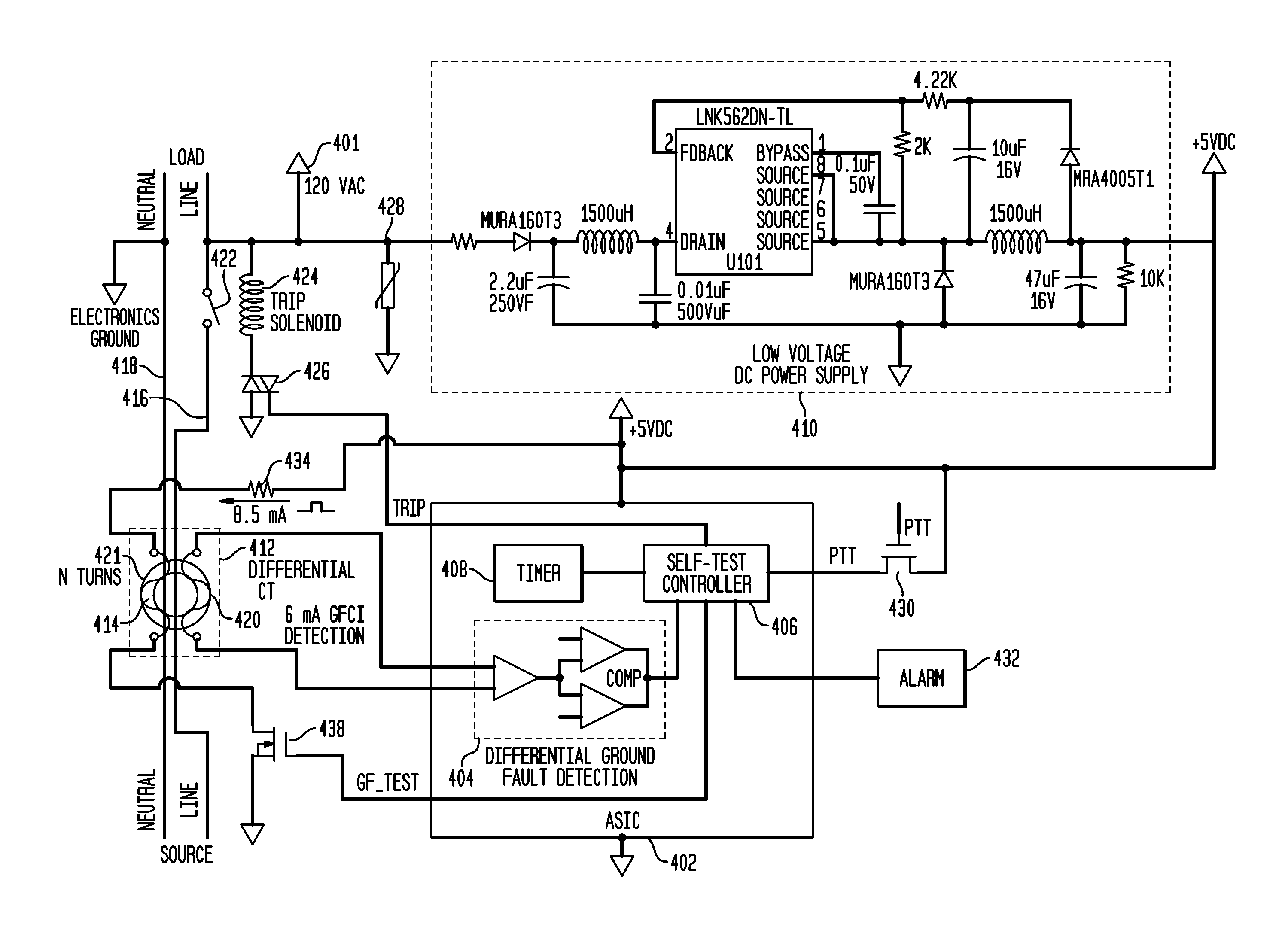
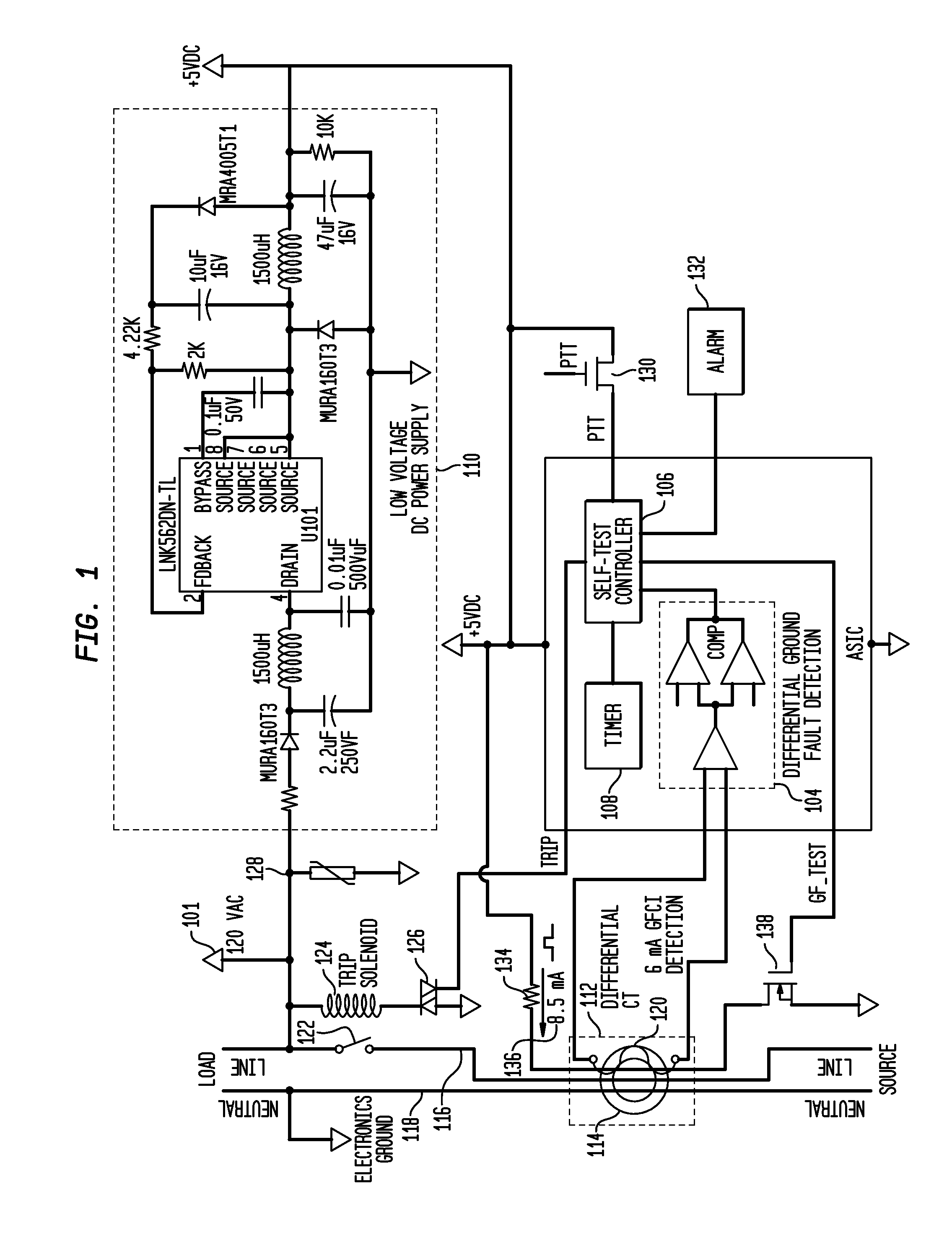
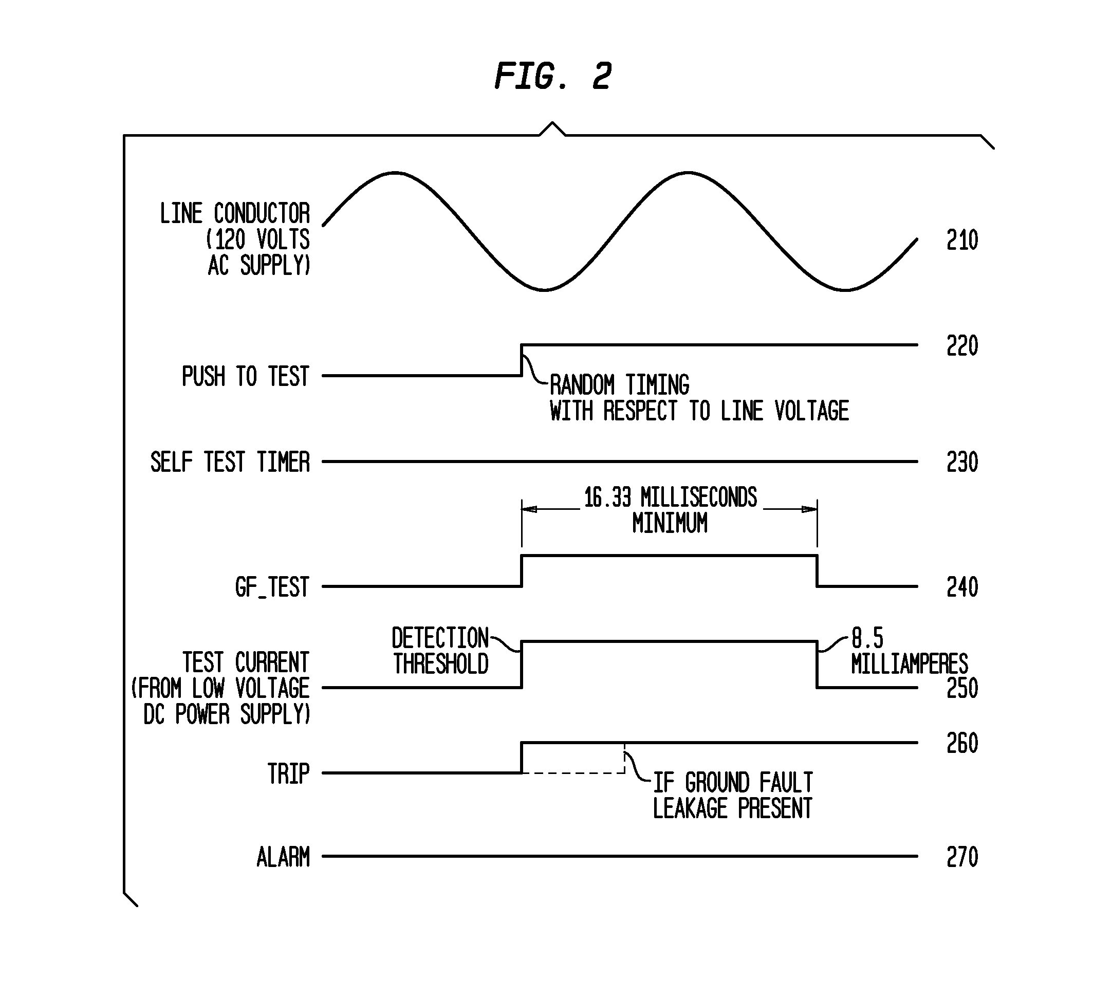
[0024]The present invention relates to a supervisory circuit for testing Ground Fault Circuit Interrupt (GCFI) devices. Many GFCI devices have a “test” button for verifying the health of a device. Test methods may create a small imbalance by passing a stimulus signal current through the core of the differential transformer. For example, pressing the test button may cause the 120 volt AC power supply to be drawn across a 15 K resistor along a test wire that passes through the differential transformer. In this example, a current of 8 mA (milliamperes rms), which is greater than the 6 mA leakage current detection requirement for GFCI circuits, passes through the differential transformer. The differential transformer and detection circuitry in a properly functioning device would detect the test current as an imbalance and cause the circuit to trip. The tester interprets this result as meaning the circuit breaker device is working safely and correctly. If the circuit breaker does not tri...


PUM


Abstract

An apparatus and method for a supervisory circuit for a ground fault detection device or ground fault circuit interrupt (GFCI) device is disclosed in which is a test stimulus signal for a self test of the GFCI device is generated on a second secondary winding on a toroid of a differential current transformer. The GFCI device includes line and neutral conductors configured to connect an AC power source and a load. A differential current transformer includes a toroid, through which the line and neutral conductors pass, a first secondary winding wound on the toroid to generate a current in response to an imbalance of magnetic flux in the toroid, and a second secondary winding wound on the toroid. A differential ground fault detector is electrically connected to the first secondary winding of the differential current transformer to compare current generated in the secondary winding to a trip threshold. A controller is configured to control a test stimulus signal to be generated in the second secondary winding wound on the toroid of the differential current transformer.

Description

[0001]This application claims the benefit of U.S. Provisional Application No. 61 / 313,889, filed Mar. 15, 2010, the disclosure of which is herein incorporated by reference.BACKGROUND OF THE INVENTION[0002]The present invention relates to ground fault detection circuits and more particularly, to testing a ground fault detection circuit using a stimulus signal on a second winding added to a differential current transformer of a ground fault detection circuit.[0003]Ground Fault Circuit Interrupt (GFCI) devices detect the presence of ground current faults and grounded neutral faults, and interrupt power in AC power systems if such faults are detected. Accordingly, GFCI devices provide protection from electrocution and are typically used in receptacles in kitchens, bathrooms, and outdoor receptacles where there may be water or moisture that can pose a risk of electrocution. GFCI devices are also used in circuit breakers that protect these same areas of residential buildings. GFCI devices ...

Claims


Application Information

Patent Timeline
Patent Type & Authority Applications(United States)
IPC IPC(8): G01R31/02G08B21/00
CPCH02H3/335
Inventor KINSEL, HUGH T.ENDOZO, JOSELITO
Owner SIEMENS IND INC
Why Eureka
Try Eureka