
Radar level gauge with improved radar window

a technology of radar window and level gauge, which is applied in the direction of using reradiation, testing/calibration of speed/acceleration/shock measurement devices, liquid/fluent solid measurement, etc., can solve the problems of mechanical size of the opening and exceed the pressure in the tank, and achieve the effect of enduring higher pressur

Active Publication Date: 2011-09-15
ROSEMOUNT TANK RADAR
View PDF6 Cites 22 Cited by
  • Summary
  • Abstract
  • Description
  • Claims
  • Application Information

AI Technical Summary

Benefits of technology

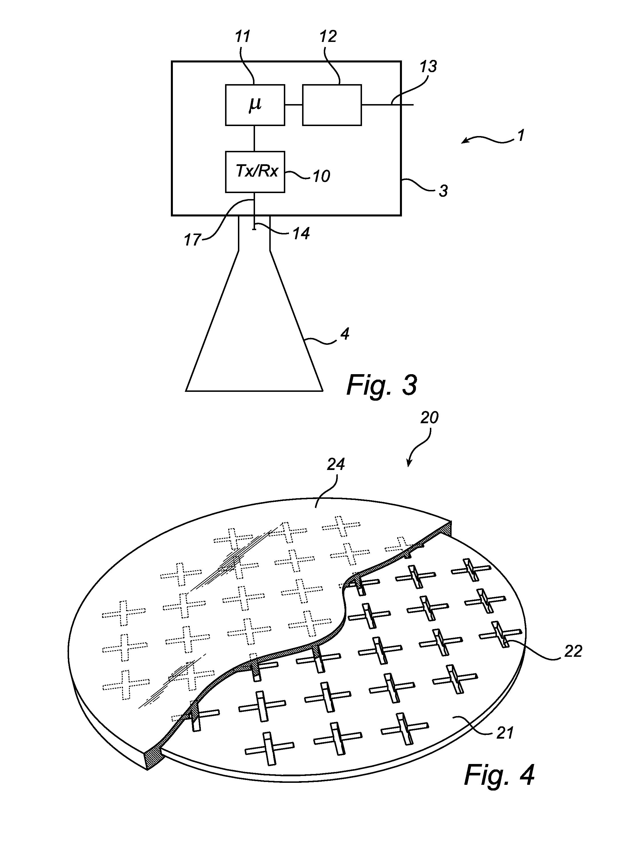
The present invention provides a radar window that can withstand higher pressure than conventional solutions. This is achieved by using a sealing member with a metal grid layer that provides structural strength and allows transmission of microwaves. The metal grid is designed to minimize its influence on radar transmission and the antenna pattern. The sealing member can be integrated with the antenna or be a separate metal reinforced radar window that can be combined with many types of antennas. The design of the openings allows for almost full microwave transparency in a typical frequency band for radar level gauging. The thickness of the sealing member can vary across its surface to obtain a lens effect.

Problems solved by technology

A challenge with such a design, however, is that it requires an opening in the tank corresponding to the antenna cross section, typically in the range of 50-400 mm.
The size of the opening can be a mechanical problem, if the opening has to withstand high pressure, especially if the temperature is high enough to cause an insulating material covering at least a part of the antenna opening to lose some of its strength.
However, in some applications the pressure in the tank exceeds that which the PTFE window seal disclosed in U.S. Pat. No. 6,325,391 can withstand, in particular when the temperature is high.

Method used


Image

  • Radar level gauge with improved radar window
  • Radar level gauge with improved radar window
  • Radar level gauge with improved radar window

Examples


Embodiment Construction

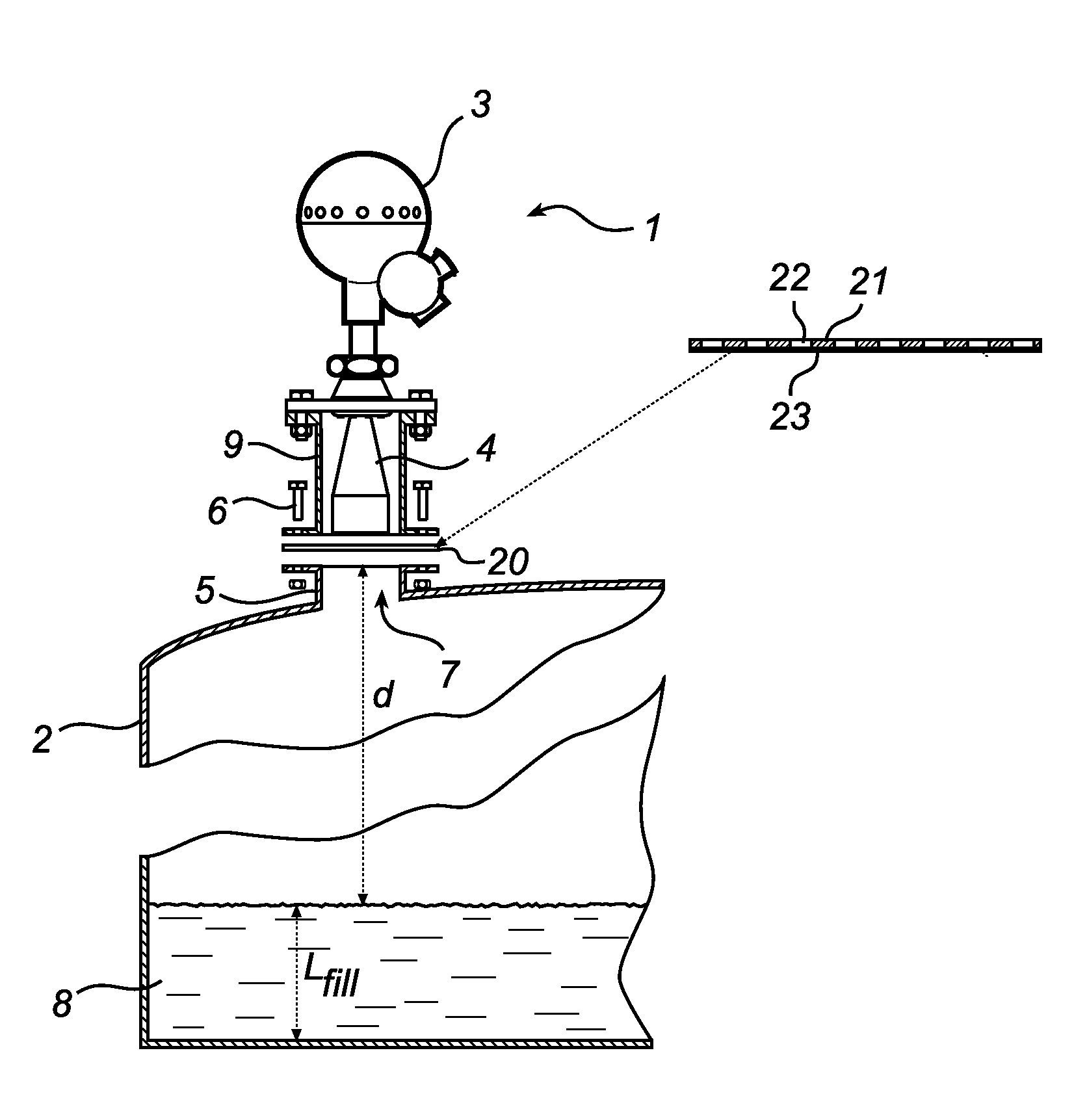
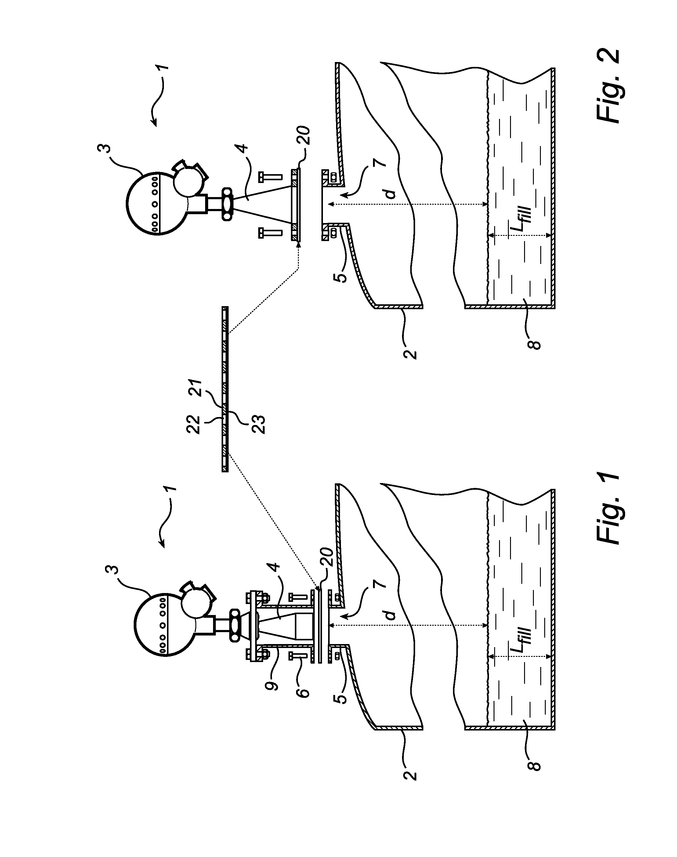
[0024]FIGS. 1 and 2 schematically illustrate a radar level gauge (RLG) 1 mounted to a tank 2. The RLG 1 comprises a measurement electronics unit 3 and an antenna 4. The radar level gauge system 1 is mounted on a flange 5 of the tank 2, by bolts 6 or any other means considered appropriate for the current conditions. The RLG 1 is thereby secured on top of a tank opening 7, in a measuring position fixed relative the bottom of the tank 2.

[0025]The RLG 1 is arranged to determine the distance d between a reference position and an interface between different materials in the tank, by transmitting signals into the tank, receiving signals reflected from the tank, and analyzing a relationship between transmitted and received signals.

[0026]This distance d may be used to perform measurements of a process variable in the tank 2, such as the filling level LFILL of a filling material 8 in the tank 2. Typically, the material 8 is a liquid content stored in the tank, e.g. oil, refined products, chem...


PUM


Abstract

A radar level gauge for determining the filling level of a product in a tank, comprising a transceiver for transmitting and receiving microwaves, processing circuitry connected to the transceiver and adapted to determine the filling level, an antenna connected to said transceiver and arranged to emit and receive microwaves through an opening of the tank, and a microwave transmissive sealing member adapted to cover said opening and to provide pressure sealing of the tank. The sealing member comprises a metal grid layer providing structural strength, which metal grid layer has sealed openings formed to allow transmission of microwaves.The tank opening is thus divided into a number of smaller openings by the metal grid, thereby improving the mechanical strength of the sealing member. At the same time, the sealing member is designed to maintain its pressure sealing properties, e.g. by suitable dielectric filling of the openings.

Description

FIELD OF THE INVENTION[0001]The present invention relates to a radar level gauge system using electromagnetic waves for measuring a level of a surface of a product in a container.BACKGROUND OF THE INVENTION[0002]Radar level gauges (RLGs) are suitably used for making non-contact measurements of the level of products such as process fluids, granular compounds and other materials contained in a tank. An example of such a radar level gauge can include a transceiver for transmitting and receiving microwaves, an antenna arranged to direct microwaves towards the surface and to return microwaves reflected by the surface to the transceiver, and processing circuitry adapted to determine the level based on a relation between microwaves transmitted and received by the transceiver.[0003]In some applications, the antenna is mounted inside the tank and is exposed to the tank contents and environment. However, in some cases it is desirable to insulate the RLG and its antenna from the tank contents....

Claims


Application Information

Patent Timeline
Patent Type & Authority Applications(United States)
IPC IPC(8): G01S13/08F16J15/12
CPCH01Q1/225G01F23/284
Inventor EDVARDSSON, OLOVLARSSON, STIG
Owner ROSEMOUNT TANK RADAR
Learn More