Illuminating device and liquid crystal display device

a technology of liquid crystal display and illumination device, which is applied in the direction of lighting and heating apparatus, instruments, spectral modifiers, etc., can solve the problems of half the backlight light being absorbed by the polarizer, i.e., lost, etc., and achieve the effect of increasing the degree of polarization of light emitted and increasing the use efficiency of light emitted

Active Publication Date: 2011-09-15
JAPAN DISPLAY INC +1
View PDF12 Cites 73 Cited by
  • Summary
  • Abstract
  • Description
  • Claims
  • Application Information

AI Technical Summary

Benefits of technology

029]According to the present invention, an illuminating device is capable of efficiently increasing a degree of polarization of light emitted from a light guide plate.<
030]According to the present invention, a liquid crystal display device is capable of increasing use efficiency of light emitted from a backlight.B

Problems solved by technology

That is, in the liquid crystal display device, if the backlight light is unpolarized light, about half of the backlight light is absorbed by the polarizers, i.e., is lost.

Method used


Image

  • Illuminating device and liquid  crystal display device
  • Illuminating device and liquid  crystal display device
  • Illuminating device and liquid  crystal display device

Examples


first embodiment

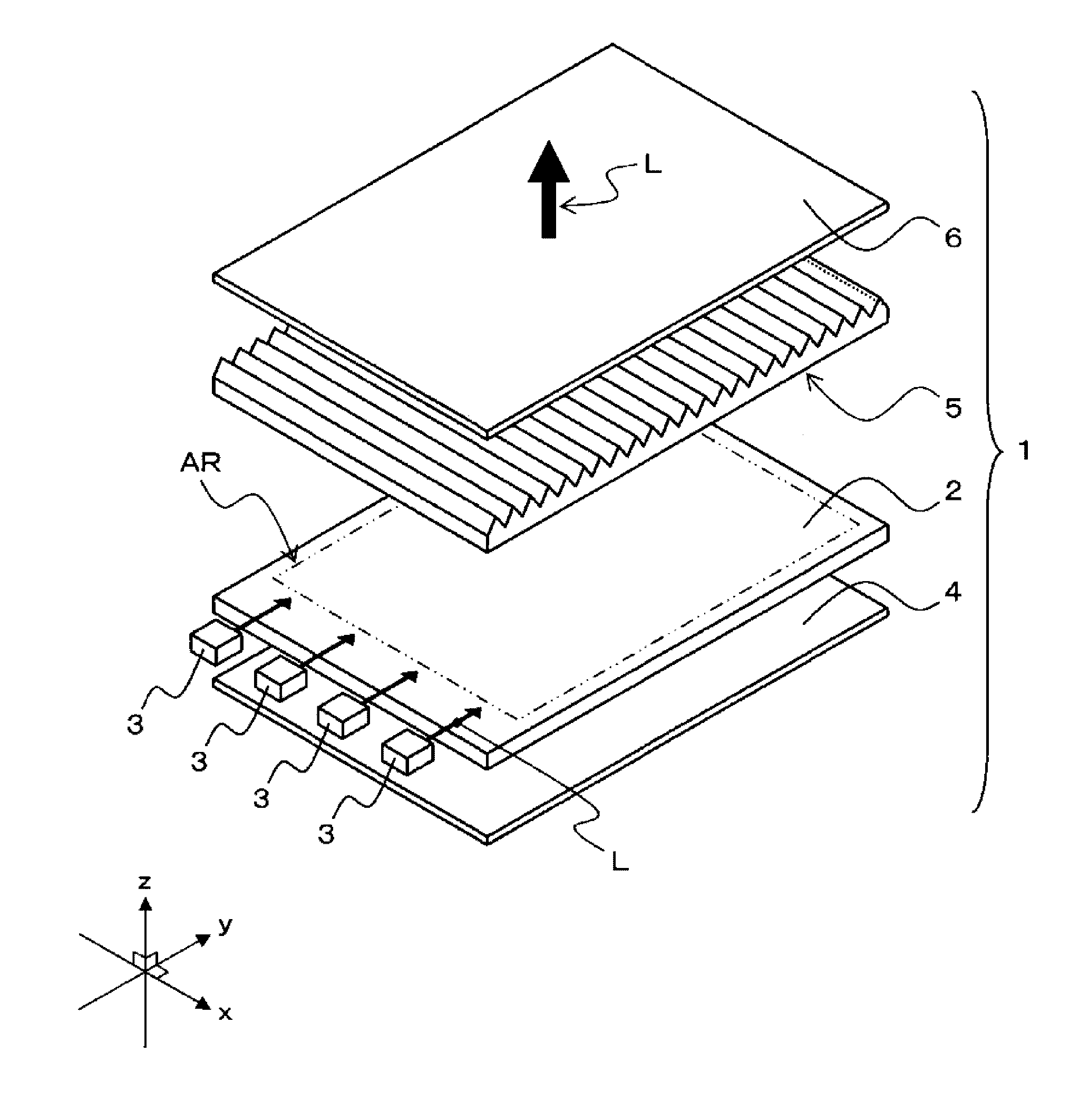
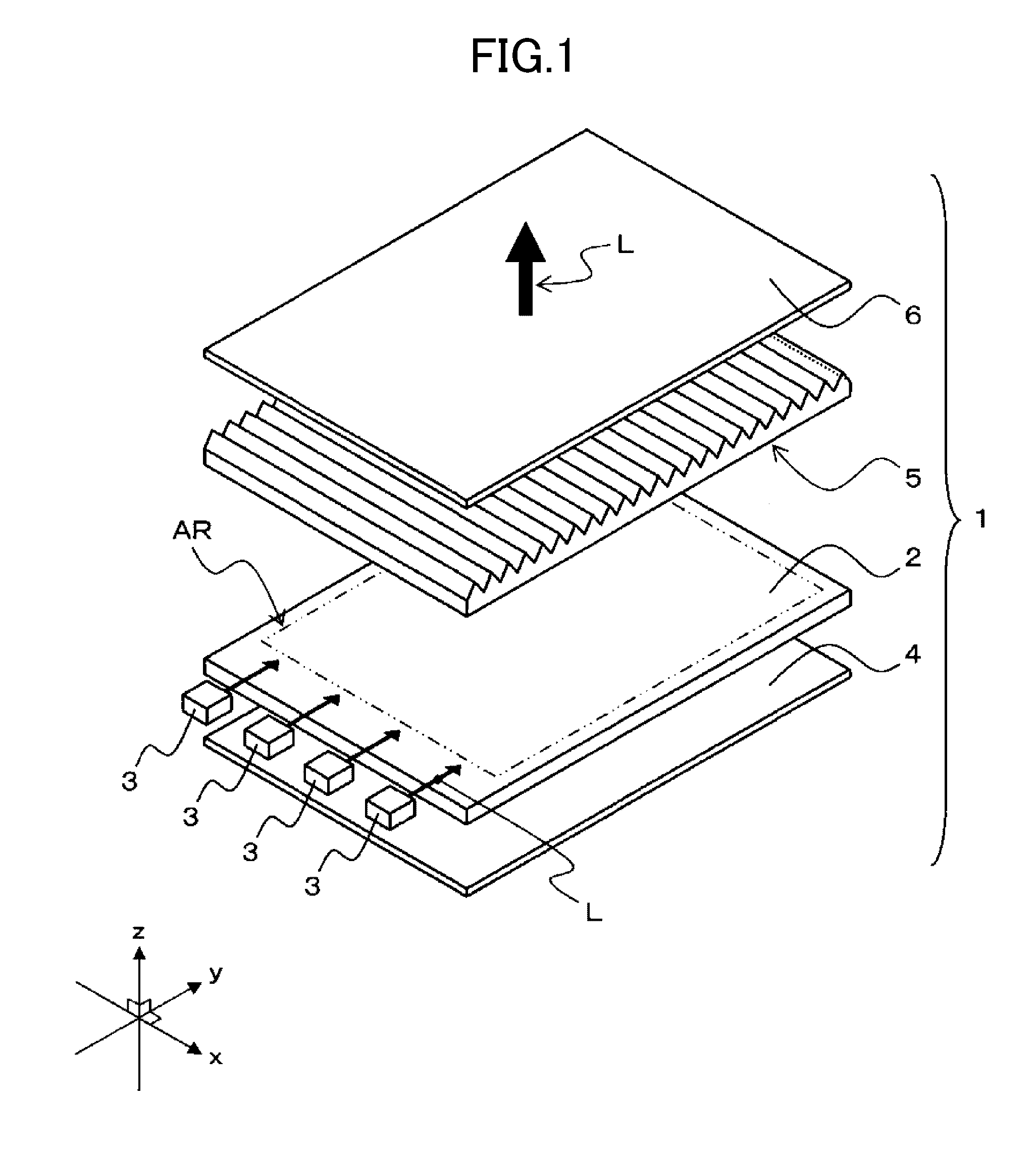
[0085]FIGS. 1 and 2 are schematic views showing a general configuration of an illuminating device according to a first embodiment of the present invention.

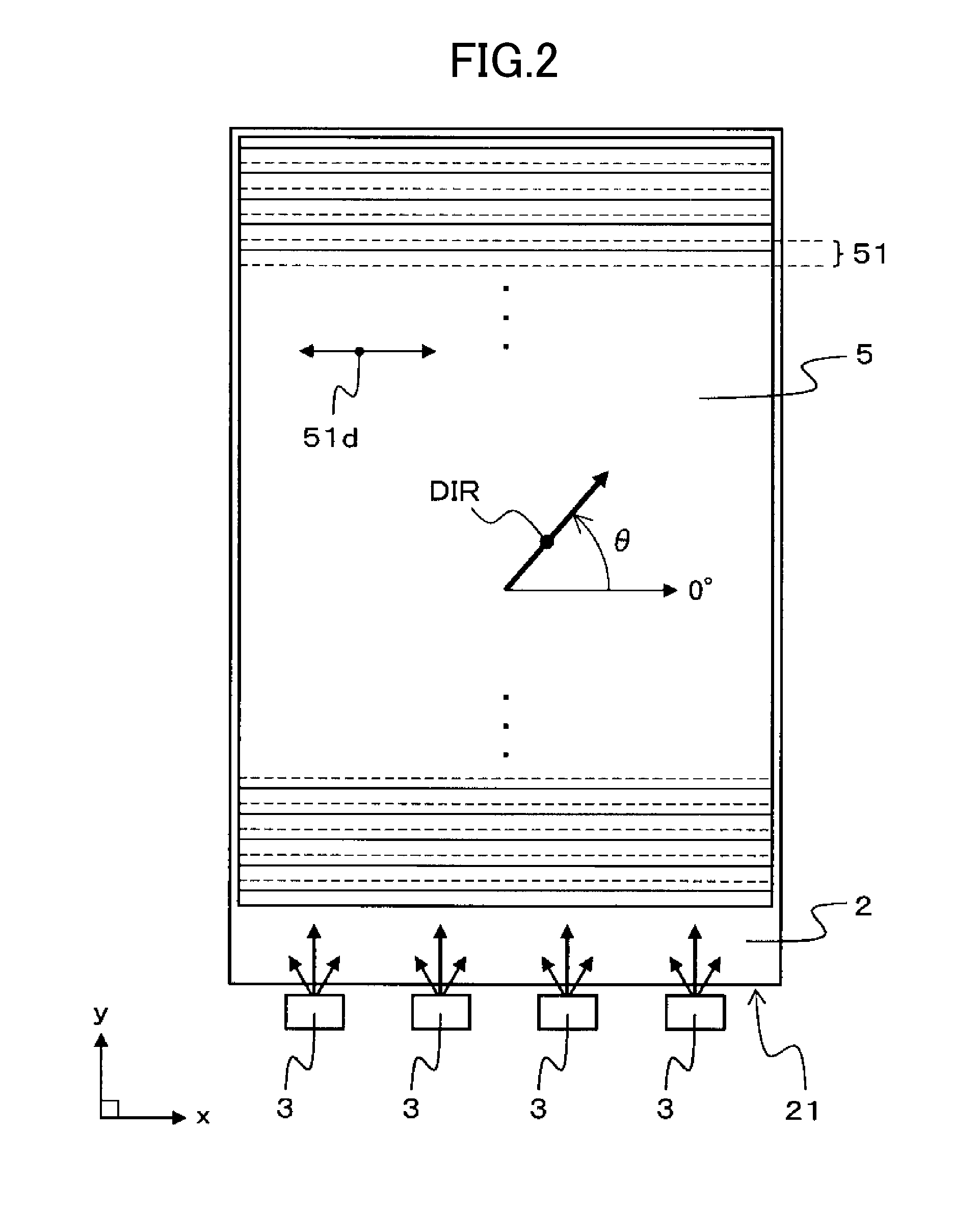
[0086]FIG. 1 is a schematic perspective view showing a general configuration of main portions of the illuminating device according to the first embodiment of the present invention. FIG. 2 is a schematic plan view showing an example of a planar configuration of the illuminating device.

[0087]An illuminating device 1 according to the first embodiment includes, for example, a light guide plate 2, a plurality of light sources 3, a reflection sheet 4, a prism sheet 5 and a diffusion sheet 6, as shown in FIGS. 1 and 2.

[0088]The light guide plate 2 is a transparent plate-like optical part to convert light L emitted from the light sources 3 into a surface light ray and has Configuration 1 and Configuration 2 as described earlier. The light guide plate 2 is interposed between the reflection sheet 4 and the prism sheet 5 and is configured to...

second embodiment

[0176]FIGS. 23 to 25 are schematic views showing an example of a general configuration of a light guide plate in an illuminating device according to a second embodiment of the present invention.

[0177]FIG. 23 is a schematic perspective view showing an example of a shape of a rear side of a light guide plate according to the second embodiment of the present invention. FIG. 24 is a schematic sectional view showing an example of a shape of a section of the light guide plate in a section in parallel to a yz plane in FIG. 23. FIG. 25 is a schematic sectional view showing an example of a shape of a section of the light guide plate in a section in parallel to an xz plane in FIG. 23.

[0178]x, y and z-axis directions in an xyz coordinate system shown in FIG. 23 are the same as the x, y and z-axis directions in the xyz coordinate system shown in FIG. 1, respectively.

[0179]In the second embodiment, a modification of the polarization state converting structure 25 provided in the rear side of the ...

third embodiment

[0193]FIGS. 27 to 29 are schematic views showing an example of a general configuration of a light guide plate in an illuminating device according to a third embodiment of the present invention.

[0194]FIG. 27 is a schematic perspective view showing an example of a shape of a rear side of the light guide plate according to the third embodiment of the present invention. FIG. 28 is a schematic sectional view showing an example of a shape of a section of the light guide plate in a section in parallel to a yz plane in FIG. 27. FIG. 29 is a schematic sectional view showing an example of a shape of a section of the light guide plate in a section in parallel to an xz plane in FIG. 27.

[0195]x, y and z-axis directions in an xyz coordinate system shown in FIG. 27 are the same as the x, y and z-axis directions in the xyz coordinate system shown in FIG. 1, respectively.

[0196]In the third embodiment, a further modification of the polarization state converting structure 25 provided in the rear side ...


PUM

PropertyMeasurementUnit
apex angleaaaaaaaaaa
inclination angleaaaaaaaaaa
refractive indexaaaaaaaaaa

Abstract

An illuminating device includes: a light source; a light guide plate which converts light emitted from the light source into a surface light ray and emits the surface light ray through a front surface of the light guide plate; and an optical sheet which changes a propagation direction of the surface light ray emitted from the light guide plate. The light source is arranged in end surface different from the front surface in the light guide plate. A polarization state converting structure to convert a polarization state of the light propagating through the light guide plate is provided in a surface opposing the front surface in the light guide plate. The polarization state converting structure contains an inclination plane having a ridge line in a direction different from a direction in parallel to the longitudinal direction of the end surface.

Description

CROSS-REFERENCE TO RELATED APPLICATION[0001]The present application claims priority from Japanese application JP2010-056186 filed on Mar. 12, 2010, the content of which is hereby incorporated by reference into this application.BACKGROUND OF THE INVENTION[0002]1. Field of the Invention[0003]The present invention relates to an illuminating device and a liquid crystal display device, and more particularly, to an illuminating device which generates a surface light ray using a light guide plate, and a liquid crystal display device including the illuminating device used as a backlight.[0004]2. Description of the Related Art[0005]A display device is a medium to show information to persons visually and is very important for humans in the today's highly information-oriented society. In particular, the performance of a liquid crystal display device has been remarkably improved in recent years and the device is being employed as a display device equipped in a mobile phone terminal, a display d...

Claims


Application Information

Patent Timeline
Patent Type & Authority Applications(United States)
IPC IPC(8): G02F1/1335F21V9/14
CPCG02B6/0038G02B6/0036G02B6/0056G02B6/0068G02B6/0073G02F1/133615
Inventor ADACHI, MASAYASUGITA, TATSUYA
Owner JAPAN DISPLAY INC
Why Eureka
Try Eureka