X-Ray Imaging Apparatus

a technology of x-ray imaging and ct imaging, which is applied in the direction of instruments, diaphragms for radiation diagnostics, radiation beam directing means, etc., can solve the problems of reducing resolution, difficult to optimally increase the sharpness of x-ray images, and difficulty in improving image quality, so as to reduce the opening width of the opening portion, improve the accuracy, and reduce the effect of cos

Active Publication Date: 2011-09-15
MORITA MFG CO LTD
View PDF2 Cites 15 Cited by
  • Summary
  • Abstract
  • Description
  • Claims
  • Application Information

AI Technical Summary

Benefits of technology

[0037]In the X-ray imaging apparatus according to the sixth aspect, the same effects as those of the X-ray imaging apparatuses according to the third to fifth aspects can be obtained, and additionally an effect that the focal spot size can be changed with enhanced accuracy can be obtained.
[0038]In a seventh aspect, in the X-ray imaging apparatus according to any one of the third to sixth aspects: a restriction section restricts the X-ray beam, the restriction section restricting a range of radiation of the X-ray beam by allowing a part of the X-ray beam to pass therethrough in an op

Problems solved by technology

Therefore, it has been difficult to improve the image quality by, for example, increasing the sharpness of an X-ray image or reducing blurring (so-called defocusing or reflection blurring), because when imaging is performed using a narrowly-spread X-ray beam, an X-ray passing through a certain spot on an X-ray emission path is largely dispersed on an X-ray detection surface so that the resolution is lowered.
Thus, it is difficult to optimally increase the sharpness of an X-ray image in accordance with the type of imaging.
It is impossible that the sharpness of an X-ray image is increased in an imaging m

Method used


Image

  • X-Ray Imaging Apparatus
  • X-Ray Imaging Apparatus
  • X-Ray Imaging Apparatus

Examples


Embodiment Construction

[0070]Hereinafter, some preferred embodiments will be described in detail with reference to the accompanying drawings. Any configuration described in these preferred embodiments is merely illustrative, and should not be construed as limiting the scope of the present invention.

1. First Preferred Embodiment

1.1. Outline

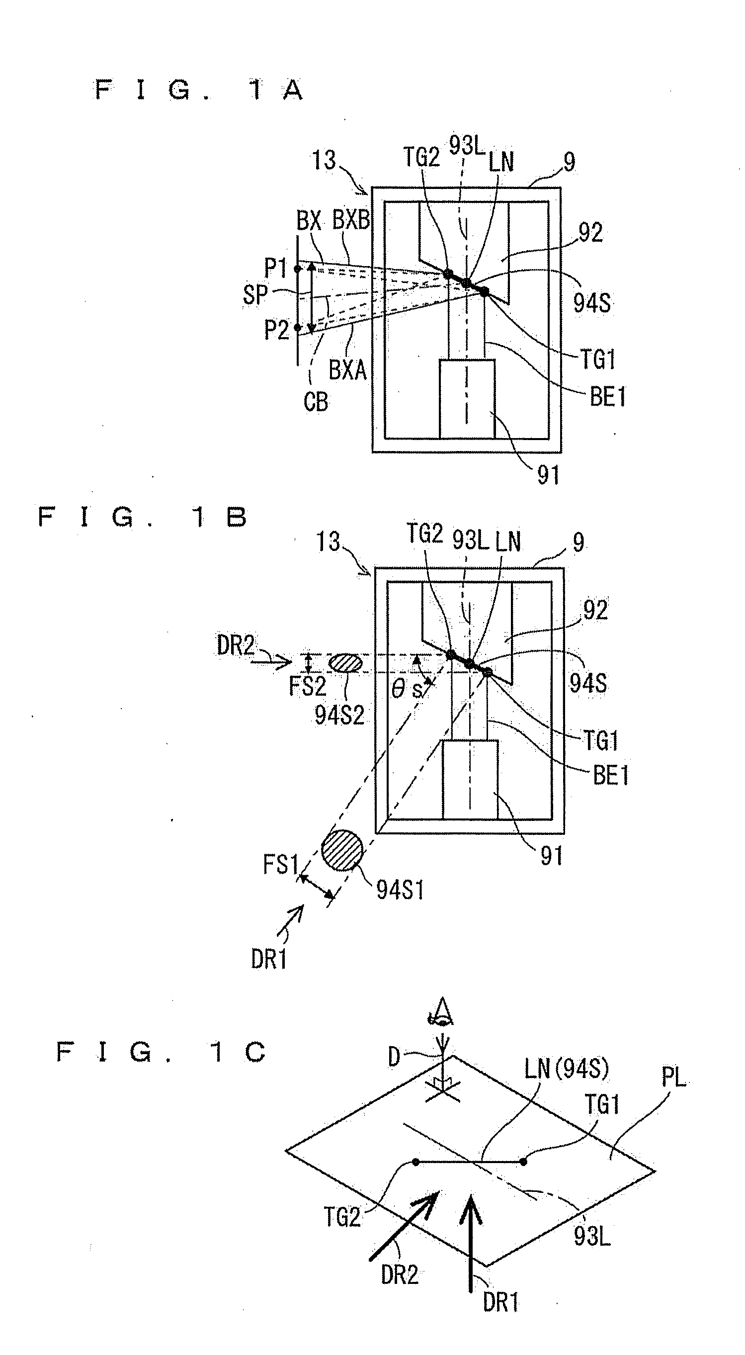
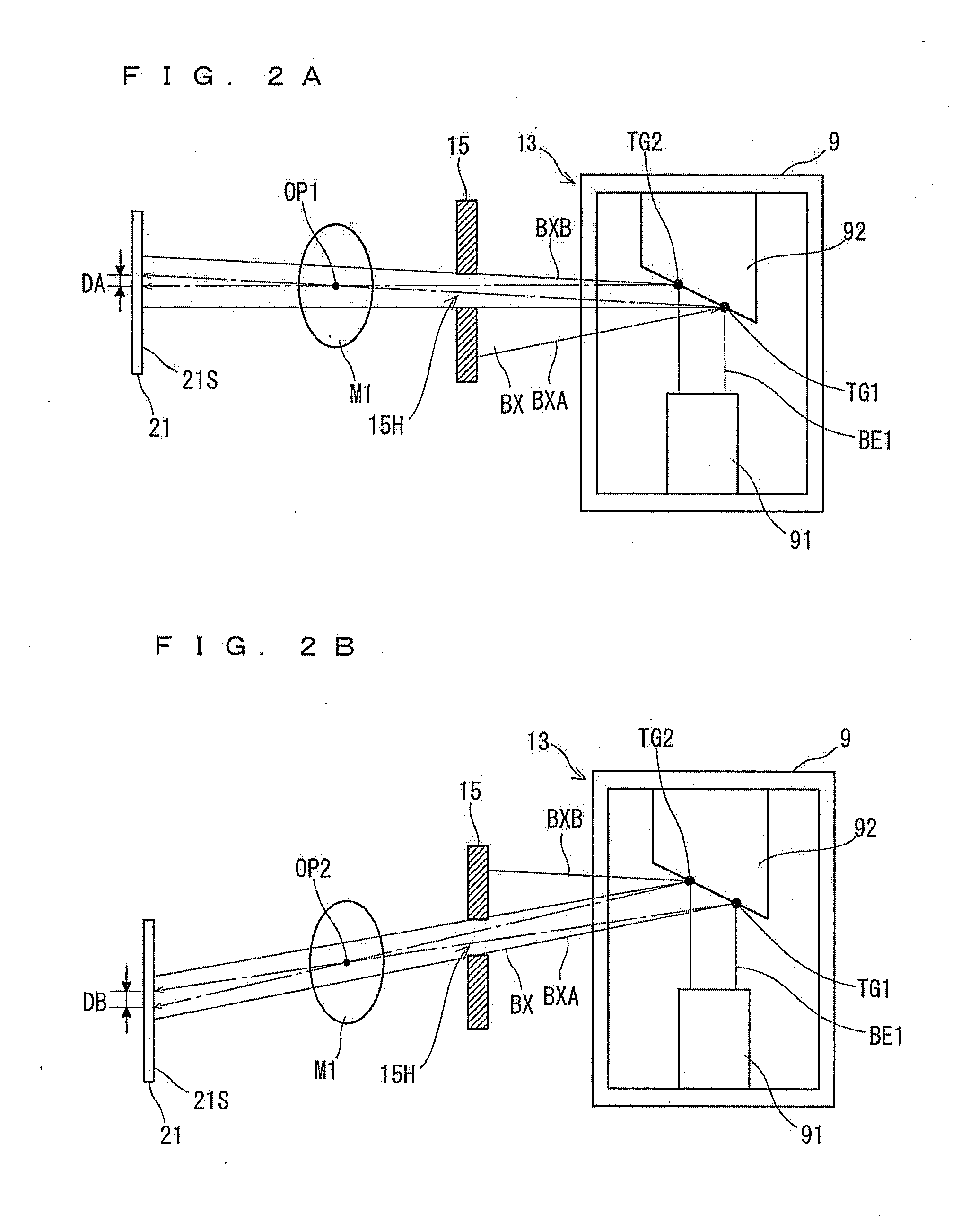
[0071]FIGS. 1A, 1B, 1C, 2A, and 2B are diagrams schematically showing an X-ray tube 9 according to a first preferred embodiment. FIGS. 1A, 1B, 2A, and 2B are diagrams schematically showing the X-ray tube 9 as viewed along a line-of-sight direction D which is a direction of seeing an inclined surface of a target surface 94S as shown in FIG. 1C.

[0072]As shown in FIG. 1A, in the X-ray tube 9 serving as an X-ray generation source, a cathode 91 including a filament and an anode 92 arranged at a distance from the cathode 91 are provided. A surface of the anode 92 opposed to the cathode 91 is formed as an inclined surface inclined at a predetermined angle relative to a straigh...


PUM


Abstract

An X-ray imaging apparatus includes an X-ray generation part, an X-ray detection part, and a revolution drive mechanism. The X-ray generation part has an X-ray generator including a cathode and an anode, and emits an X-ray beam from the X-ray generator. The X-ray detection part detects the X-ray beam. The revolution drive mechanism performs X-ray imaging by revolving the X-ray generation part and the X-ray detection part around the object while the X-ray generation part and the X-ray detection part are opposed to each other with said object interposed therebetween. The X-ray imaging apparatus controls a restriction part to thereby restrict an X-ray transmission in such a manner that the focal spot size of an X-ray beam used in X-ray CT imaging of a relatively narrow imaging region is smaller than the focal spot size of an X-ray beam used in X-ray CT imaging of a relatively large imaging region.

Description

BACKGROUND OF THE INVENTION[0001]1. Field of the Invention[0002]The present invention relates to a technique for X-ray CT imaging using an X-ray, and particularly to a technique of improving the resolution of a CT image.[0003]2. Description of the Background Art[0004]In the medical field, an X-ray imaging apparatus allowing various imaging modes to be performed by itself alone is used. For example, in the dental field, Japanese Patent Application Laid-Open No. 9-122118 (1997) discloses a multi-purpose type X-ray imaging apparatus which provides both a panoramic imaging mode and a CT imaging mode. In the panoramic imaging mode, a curved dental arch is imaged as an image developed in a plane. In the CT imaging mode, a tomographic image of a region of interest in a living organ is acquired.[0005]In the X-ray imaging apparatus disclosed in Japanese Patent Application Laid-Open No. 9-122118 (1997), an X-ray source and an X-ray image detection means are revolved while being opposed to eac...

Claims


Application Information

Patent Timeline
IPC IPC(8): A61B6/03G01N23/04
CPCA61B6/032A61B6/06A61B6/08H01J35/08A61B6/4476A61B6/587A61B6/14H01J35/1017
Inventor SUZUKI, MASAKAZUYOSHIKAWA, HIDEKIHONJO, MAKOTO
Owner MORITA MFG CO LTD
Why Eureka
Try Eureka