Body-worn vital sign monitor

a vital sign and monitor technology, applied in the field of medical devices for monitoring vital signs, can solve the problems of limited capabilities, difficult to effectively monitor patients in this way, and conventional vital sign monitors, so as to improve the safety of hospitalized patients, effectively monitor patients, and minimize the corruption of vital signs

Active Publication Date: 2011-09-15
SOTERA WIRELESS
View PDF102 Cites 102 Cited by
  • Summary
  • Abstract
  • Description
  • Claims
  • Application Information

AI Technical Summary

Benefits of technology

[0012]To improve the safety of hospitalized patients, particularly those in lower-acuity areas, it is desirable to have a body-worn monitor that continuously measures all vital signs from a patient, provides tools for effectively monitoring the patient, and wirelessly communicates with a hospital's information technology (IT) network. Preferably the monitor operates algorithms featuring: 1) a low percentage of false positive alarms / alerts; and 2) a high percentage of true positive alarms / alerts. The term ‘alarm / alert’, as used herein, refers to an audio and / or visual alarm generated directly by a monitor worn on the patient's body, or alternatively a remote monitor (e.g., a central nursing station). To accomplish this, the invention provides a body-worn monitor that measures a patient's vital signs (e.g. cNIBP, SpO2, HR, RR, and TEMP) while simultaneously characterizing their activity state (e.g. resting, walking, convulsing, falling) and posture (upright, supine). The body-worn monitor processes this information to minimize corruption of the vital signs and associated alarms / alerts by motion-related artifacts.

Problems solved by technology

It can be difficult to effectively monitor patients in this way, however, because measurements are typically made every few hours, and the patients are often ambulatory and not constrained to a single hospital room.
This poses a problem for conventional vital sign monitors, which are typically heavy and unwieldy, as they are not intended for the ambulatory population.
Some companies have developed ambulatory vital sign monitors with limited capabilities (e.g. cuff-based blood pressure using oscillometry and SpO2 monitoring), but typically these devices only make intermittent, rather than continuous, measurements.
And even these measurements tend to work best on stationary patients, as they are easily corrupted by motion-related artifacts.

Method used


Image

  • Body-worn vital sign monitor
  • Body-worn vital sign monitor
  • Body-worn vital sign monitor

Examples


Embodiment Construction

System Overview

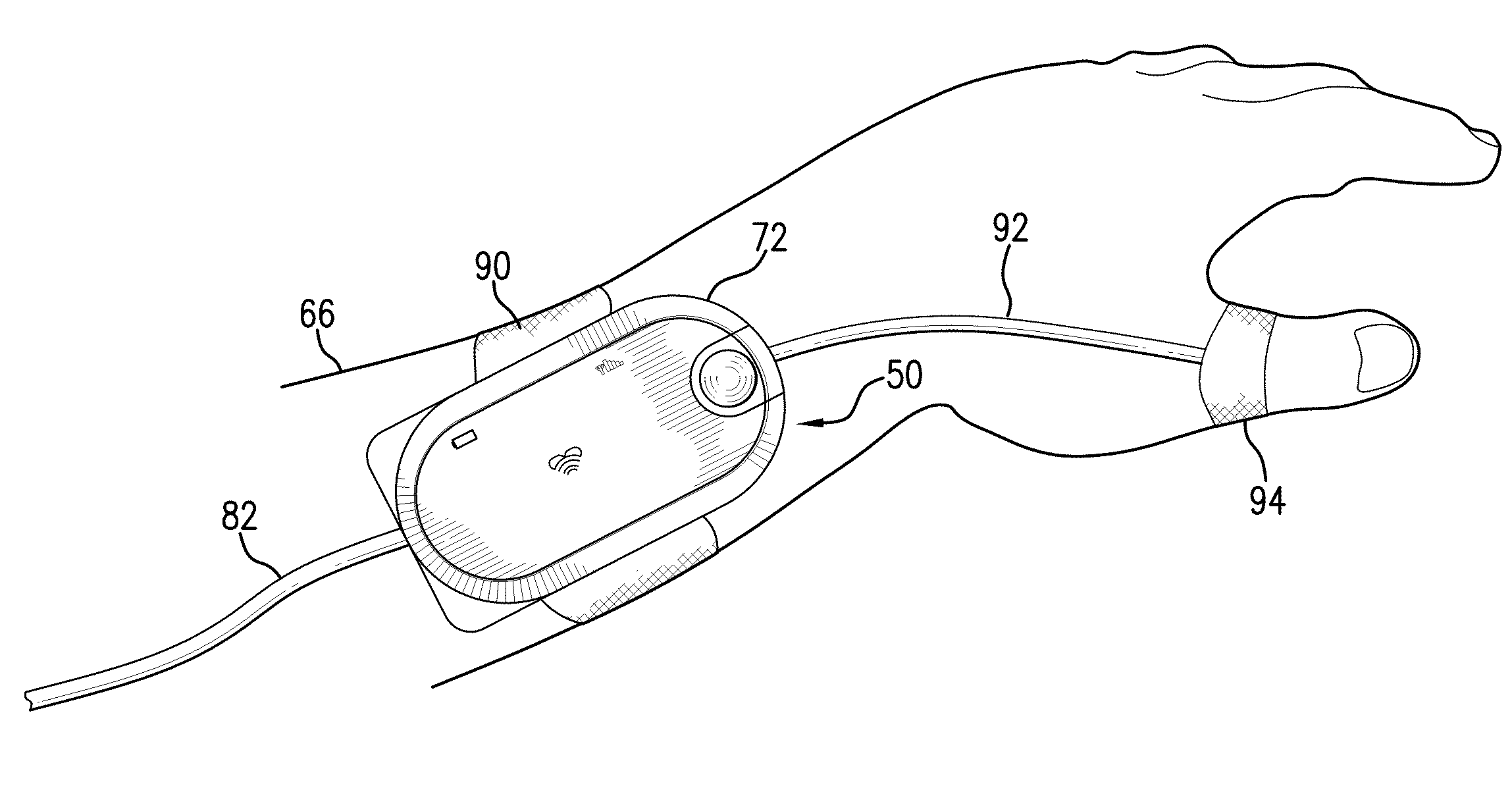
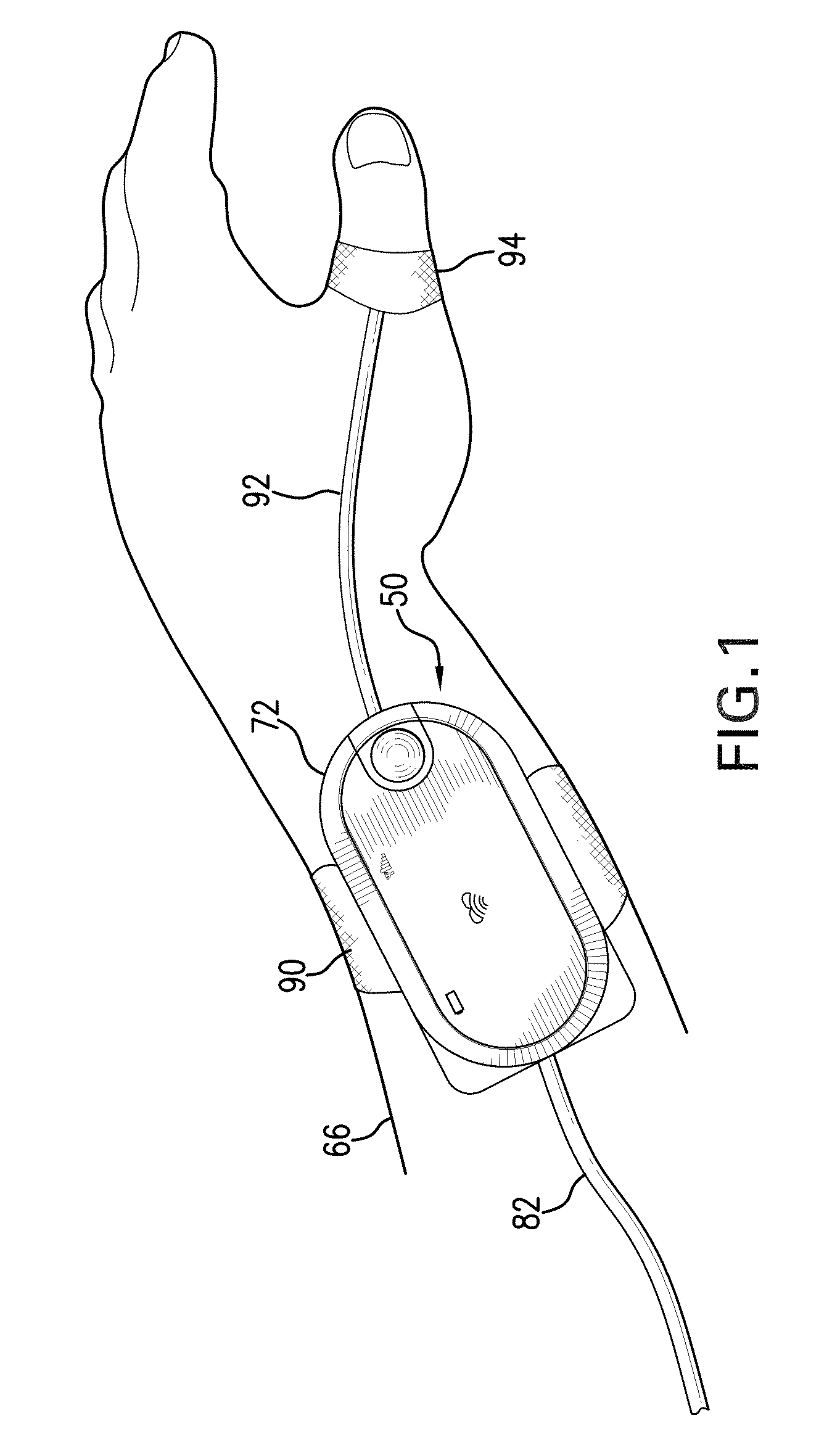
[0067]FIG. 1 shows a transceiver 72 according to the invention that attaches to a patient's wrist 66 using a flexible strap 90. The transceiver 72 connects through a first flexible cable 92 to a thumb-worn optical sensor 94, and through a second flexible cable 82 to an ECG circuit and a series of chest-worn electrodes (not shown in the figure). During a measurement, the optical sensor 94 and chest-worn electrodes measure, respectively, time-dependent optical waveforms (e.g. PPG) and electrical waveforms (e.g. ECG and IP), which are processed as described below to determine vital signs and other physiological parameters such as cNIBP, SpO2, HR, RR, TEMP, pulse rate (PR), and cardiac output (CO). Once measured, the transceiver 72 wirelessly transmits these and other information to a remote PDS and RVD. The transceiver 72 includes a touchpanel display that renders a GUI 50 which, in turn, displays the vital signs, physiological parameters, and a variety of other features...


PUM


Abstract

The invention provides a body-worn vital sign monitor that measures a patient's vital signs (e.g. blood pressure, SpO2, heart rate, respiratory rate, and temperature) while simultaneously characterizing their activity state (e.g. resting, walking, convulsing, falling) and posture (upright, supine). The monitor processes this information to minimize corruption of the vital signs and associated alarms/alerts by motion-related artifacts. It also features a graphical user interface (GUI) rendered on a touchpanel display that facilitates a number of features to simplify and improve patient monitoring and safety in both the hospital and home.

Description

CROSS REFERENCES TO RELATED APPLICATIONS[0001]This application claims the benefit of U.S. Provisional Application No. 61 / 312,624, filed Mar. 10, 2010, entitled “BODY-WORN VITAL SIGN MONITOR”, which is incorporated herein in its entirety.STATEMENT REGARDING FEDERALLY SPONSORED RESEARCH OR DEVELOPMENT[0002]Not ApplicableBACKGROUND OF THE INVENTION[0003]1. Field of the Invention[0004]The present invention relates to medical devices for monitoring vital signs, e.g., arterial blood pressure.[0005]2. Description of the Related Art[0006]Conventional vital sign monitors are used throughout the hospital, and are particularly commonplace in high-acuity areas such as the intensive care unit (ICU), emergency department (ED), or operating room (OR). Patients in these areas are generally sick and require a high degree of medical attention, typically provided by a relatively high ratio of clinicians compared to lower-acuity areas of the hospital. Outside the ICU and OR, clinicians typically measur...

Claims


Application Information

Patent Timeline
Patent Type & Authority Applications(United States)
IPC IPC(8): A61B5/00H04W4/02H04W4/029
CPCA61B5/00A61B5/411A61B5/0002H04W4/02A61B5/746A61B5/6824A61B5/7465H04W4/029
Inventor BANET, MATTMOON, JIM
Owner SOTERA WIRELESS
Why Eureka
Try Eureka