
Flue Gas Sensor With Water Barrier Member

a technology of flue gas sensor and water barrier, which is applied in the direction of instruments, measurement devices, scientific instruments, etc., can solve the problems of reducing the efficiency and heat output adversely affecting the function of the combustion device, and residential furnaces without a detection system for directly monitoring

Active Publication Date: 2011-09-22
CARRIER CORP
View PDF22 Cites 14 Cited by
  • Summary
  • Abstract
  • Description
  • Claims
  • Application Information

AI Technical Summary

Benefits of technology

[0011]In another aspect of this disclosure, a method for monitoring at least one gas in a flue gas stream of a combustion device is disclosed. The method may comprise the steps of providing a flue gas sensor in direct contact with the flue gas stream, the sensor comp...

Problems solved by technology

In addition, incomplete combustion can adversely affect the function of a combustion device, such as by decreasing its efficiency and heat output.
Traditionally, residential furnaces do not have a detection system for directly monitoring the concentration of carbon monoxide or other gasses present in combustion products due to feasibility including high cost and limited durability relative to a residential furnace.
As a result, the pressure switches only deactivate the furnace system if there is an air blockage or starvation of combustion air.
Most commercially available gas sensors are generally not used in a flue gas stream of a combustion device.
Similarly, household or industrial CO detectors based on liquid electrolyte are also known but generally operate at room temperature and are not suitable for use in most high temperature flue gas environment.
One problem associated with existing flue gas sensors is premature sensor failure.
For example, while the average design life of a residential furnace is about twenty years, existing flue gas sensors generally have a substantially shorter life span, with some sensor failure occurring within two to three years of operation.
The disparity between the life of the sensor and that of the furnace not only requires frequent service or replacement of the sensor, but also significantly affect the safe operation of the furnace, especially toward the end of the furnace life when incomplete combustion and excessive CO emission are most likely to OMIT.

Method used


Image

  • Flue Gas Sensor With Water Barrier Member
  • Flue Gas Sensor With Water Barrier Member
  • Flue Gas Sensor With Water Barrier Member

Examples


Embodiment Construction

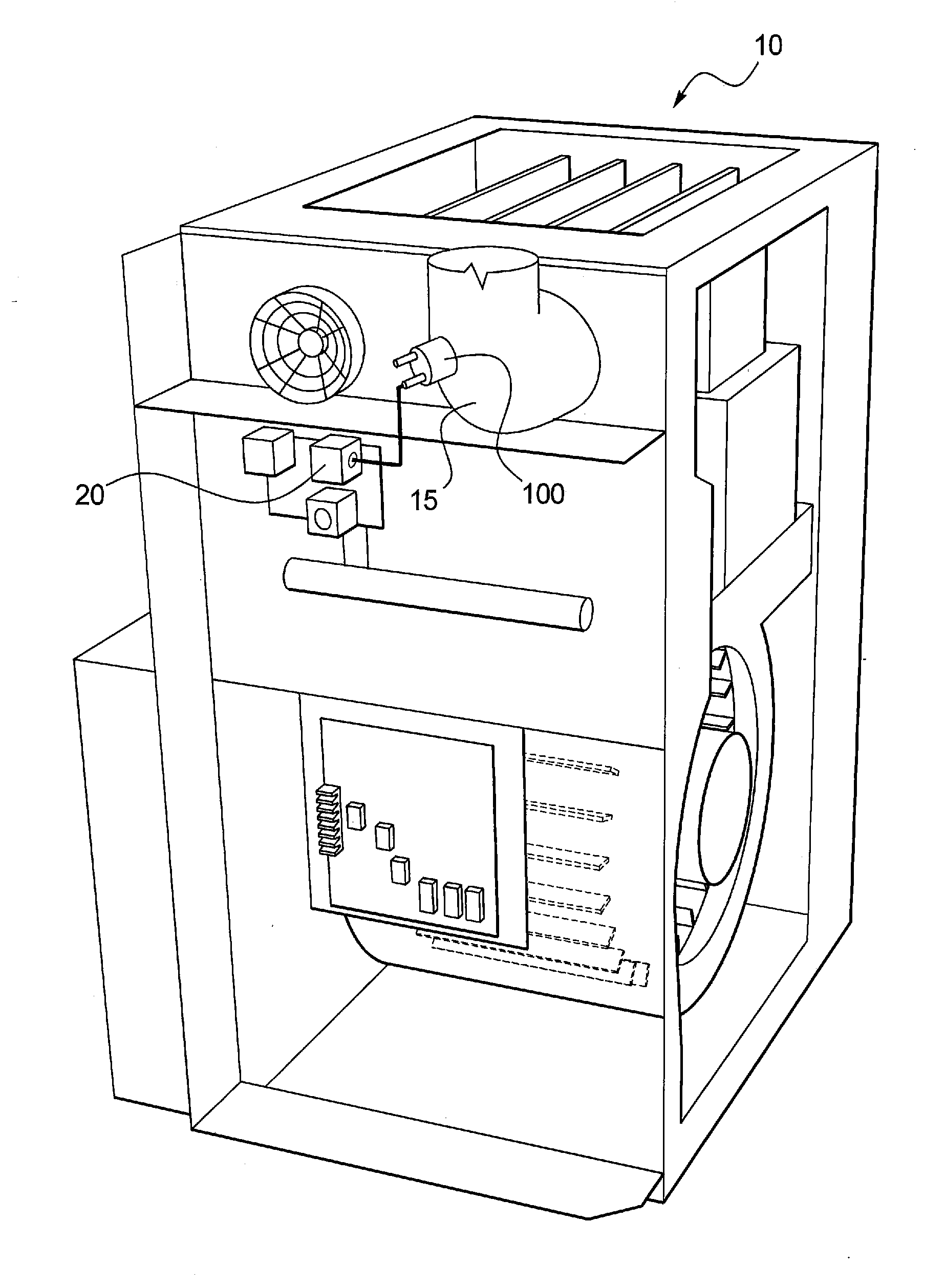
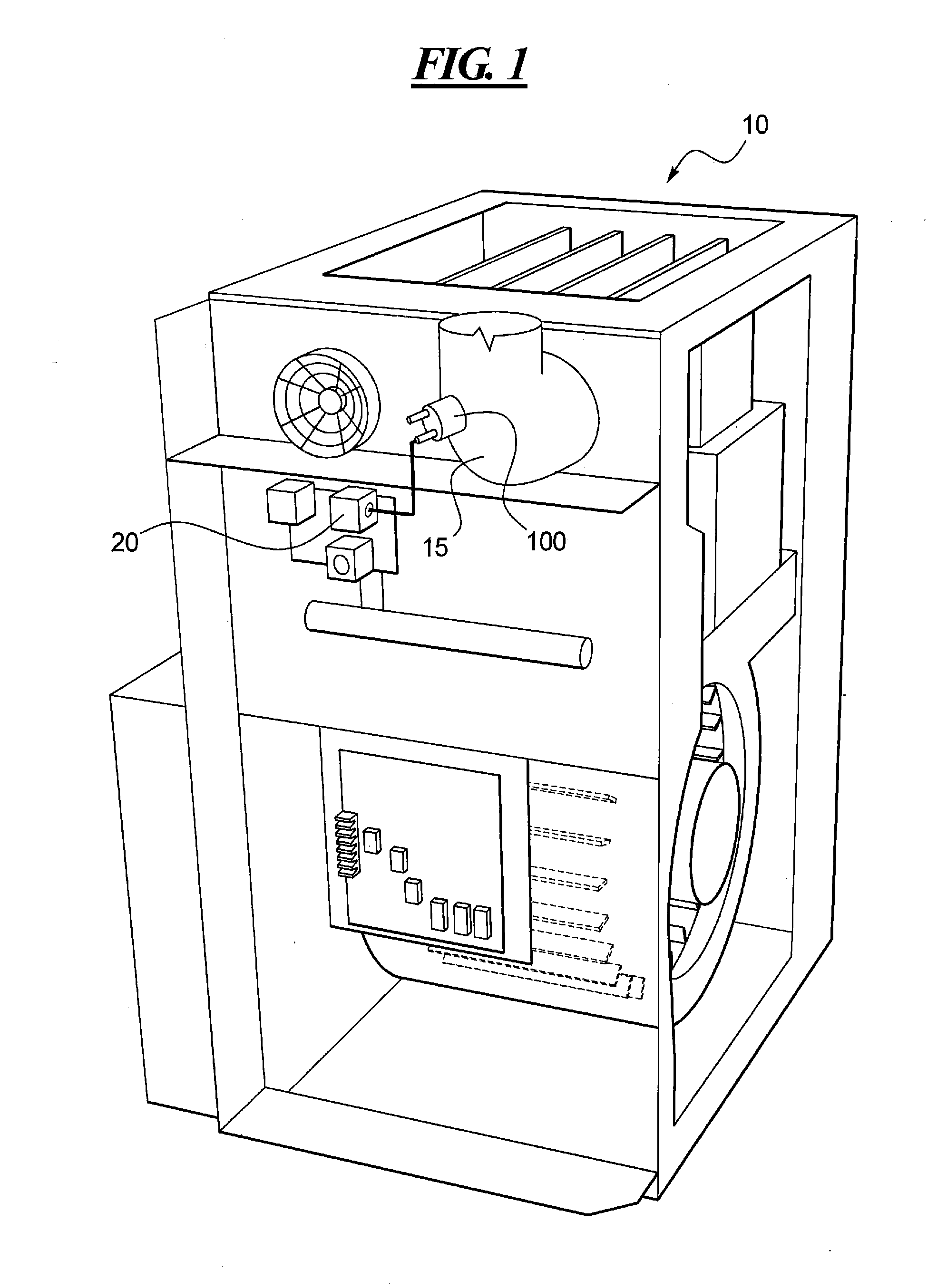
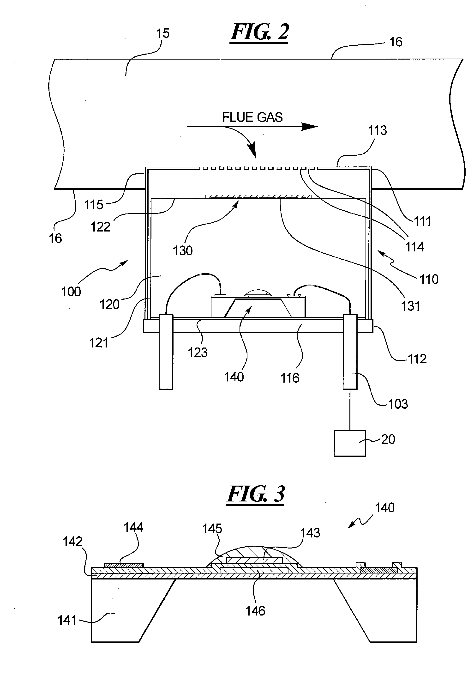
[0020]This disclosure is generally directed to a method and apparatus for monitoring at least one gas in a flue gas stream of a combustion device. As mentioned earlier, one problem associated with current flue gas monitoring techniques is the premature failure of gas sensors. Without wishing to be bound by any particular theory, it is contemplated in this disclosure that at least a substantial portion of the hot water vapor of the flue gas may come in direct contact with a gas detector, thereby causing or significantly accelerating the corrosion of its vital components, such as electrodes, metal plates, wires, etc.

[0021]The hydrogen / helium sensors for chiller tanks discussed earlier in the background section may include a membrane that prevents water or water vapor from contacting the hydrogen / helium detector. The membrane there, however, would not be contemplated as a likely solution to the problem of premature flue gas sensor failure for several reasons. First, the membrane in the...


PUM


Abstract

An improved flue gas sensor of a combustion device is disclosed. The flue gas sensor may include a housing and a gas detector disposed within the housing, wherein the gas detector detects or measures at least one gas in a flue gas stream of the combustion device. The housing may also include a water barrier member through which the at least one gas comes into contact with the gas detector. By keeping water and water vapor away from the gas detector, premature failure of the flue gas sensor caused by corrosion may be prevented.

Description

CROSS-REFERENCE TO RELATED APPLICATIONS[0001]This is a non-provisional U.S. patent application, which claims priority under 35 U.S.C. §119(e) to U.S. Provisional Patent Application Ser. No. 61 / 314,686 filed on Mar. 17, 2010, the entirety of which is incorporated by reference herein.TECHNICAL FIELD OF THE DISCLOSURE[0002]This disclosure generally relates to a method and apparatus for monitoring at least one gas in a flue gas stream and, more particularly, relates to the use of a water barrier member to prevent premature failure of flue gas sensors caused by water or water vapor in the flue gas stream.[0003]BACKGROUND OF THE DISCLOSURE[0004]Combustion devices based on hydrocarbon fuels are widely used to provide thermal, mechanical or electric energies. For example, fireplaces, ovens, furnaces, and boilers have been installed and used in commercial and residential buildings to provide heat, hot water, and other conveniences. Ideally, complete combustion occurs when hydrocarbon compoun...

Claims


Application Information

Patent Timeline
IPC IPC(8): G01N33/00
CPCG01N27/4077
Inventor ROLAND, MARC W.DEMPSEY, DANIEL J.
Owner CARRIER CORP
Learn More