Gas sensor, gas detector, and self-testing and self-correcting method therefor

A gas sensor and gas detector technology, which is used in instruments, measuring devices, scientific instruments, etc., can solve the problems that the service life is easily affected by environmental temperature and humidity, electrolyte leakage, etc., so as to achieve the correction and improvement of baseline drift and sensitivity. The effect of the service life

Inactive Publication Date: 2006-11-22
ASENSOR TECH
View PDF3 Cites 36 Cited by
  • Summary
  • Abstract
  • Description
  • Claims
  • Application Information

AI Technical Summary

Problems solved by technology

[0007] In view of the above-mentioned defects in the prior art, the present invention firstly solves the problems that electrolyte leakage occurs in traditional fuel cell gas sensors, and the service life is easily affected by ambient temperature and humidity.

Method used


Image

  • Gas sensor, gas detector, and self-testing and self-correcting method therefor
  • Gas sensor, gas detector, and self-testing and self-correcting method therefor
  • Gas sensor, gas detector, and self-testing and self-correcting method therefor

Examples


Embodiment Construction

[0041] Below in conjunction with embodiment the content of the present invention is described in detail, those skilled in the art can understand that, the present invention is not limited to following specific embodiment, also can produce multiple different concrete implementations within the scope of the technical solution of the present invention Way.

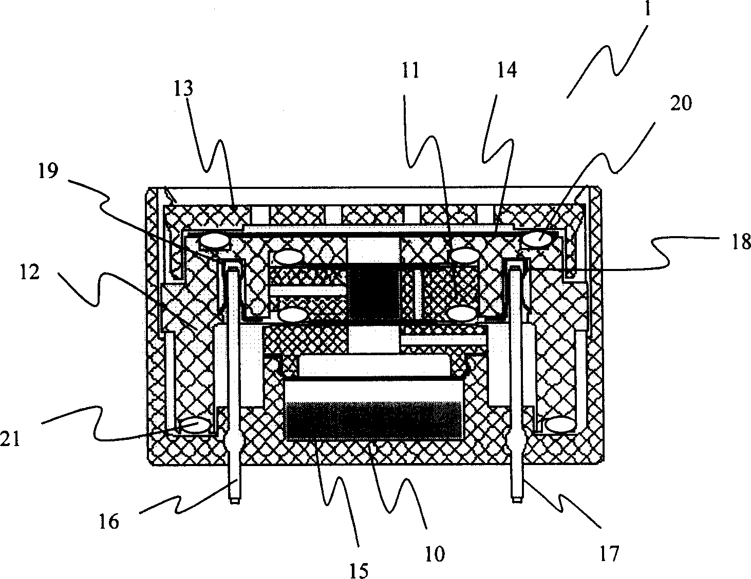
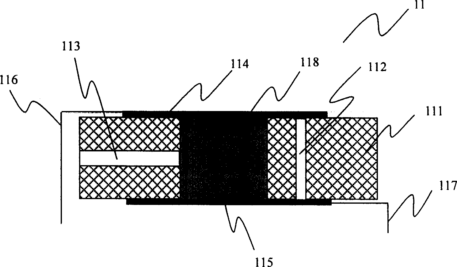
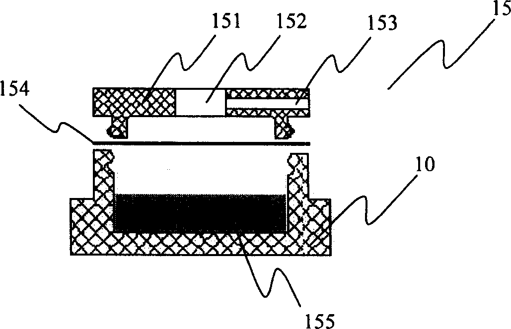
[0042] figure 1 It is a schematic diagram of the structure of the fuel cell gas sensor in the preferred embodiment of the present invention. In the fuel cell gas sensor 1, the battery core assembly 11 (for its structure, see figure 2 ) is placed in the cavity of the battery holder 12, wherein the working electrode 114 faces the central hole of the battery holder 12, so that the target gas coming from the central hole can directly reach the working electrode 114. The counter electrode 115 on the battery core assembly 11 faces the liquid storage cup assembly 15 (for details of its structure, see image 3 ) on the reservoir ...


PUM

PropertyMeasurementUnit
thicknessaaaaaaaaaa

Abstract

The related gas sensor for fuel cell comprises: based on traditional device, designing a cell core expansion hole and an air hole, using gel electrolyte instead of common liquid, adding a constant moisture device for sensor. It also uses the sensor to prepare a gas detector with self test and adjust function and free to environment effect and calibration gas source. This invention overcomes defects in prior art.

Description

technical field [0001] The present invention relates to gas sensing and detection devices, more specifically, to a fuel cell gas sensor with long life and more reliable performance, a gas detector made of this fuel cell gas sensor, and a corresponding peripheral circuit (ie, software and hardware) a method for self-testing and self-calibration of the fuel cell gas detector. Background technique [0002] The fuel cell was invented by the British William Grove in 1839 and has been widely used in gas sensors in recent decades. Generally, a fuel cell gas sensor mainly includes a working electrode (usually called an anode) and a counter electrode (usually called a cathode), and the working electrode and the counter electrode are separated by an electrolyte. Electrochemical oxidation of the "fuel" gas at the working electrode results in the flow of electrons from the anode to the cathode, ie the formation of an electrical current. Among them, the current intensity is directly pr...

Claims


Application Information

Patent Timeline
Patent Type & Authority Applications(China)
IPC IPC(8): G01N27/407G01N27/28G01N27/416G06F19/00
Inventor 秦仁炎
Owner ASENSOR TECH
Why Eureka
Try Eureka