Method of manufacturing spars, longerons and fuselage beams having a variable h cross-section

a technology of h-shaped cross-section and spars, which is applied in the direction of fuselages, transportation and packaging, other domestic articles, etc., can solve the problems of non-uniform pressure, reduced resin content of the spar, and increased porosity of the finished spar, so as to achieve high degree of geometric precision

Active Publication Date: 2011-09-22
ALENIA AERONAUTICA SPA
View PDF7 Cites 16 Cited by
  • Summary
  • Abstract
  • Description
  • Claims
  • Application Information

AI Technical Summary

Benefits of technology

[0008]The object of the present invention is therefore to overcome the aforementioned drawbacks and, specifically, to enable H-section beams to be manufactured with a high degree of geometrical precision. The invention is based on a principle according to which the pressure in the autoclave is applied uniformly to all parts of the beam to be cured, and not through rigid metal parts. These and other objects and advantages, which will be made clearer below, are achieved according to the invention.

Problems solved by technology

If the components of prior art curing tools are not perfectly connected, or if their geometry does not precisely match the beam to be produced, it is possible that non-uniform pressures, higher in certain areas and lower in others, will be applied to the uncured composite material.
This means that the areas of higher pressure will contain less resin, with a reduction in the local thickness of the spar, while the areas of lower pressure may be poorly compacted, possibly leading to porosity of the finished spar.
This problem is particularly critical in the case of spars of variable thickness.
An imperfect joint between the edge of the spar to be cured and the edge of the tool also creates empty spaces into which the resin tends to flow under pressure, thus decreasing the amount of resin in the spar and creating undesirable reductions in thickness.

Method used


Image

  • Method of manufacturing spars, longerons and fuselage beams having a variable h cross-section
  • Method of manufacturing spars, longerons and fuselage beams having a variable h cross-section
  • Method of manufacturing spars, longerons and fuselage beams having a variable h cross-section

Examples


Embodiment Construction

)

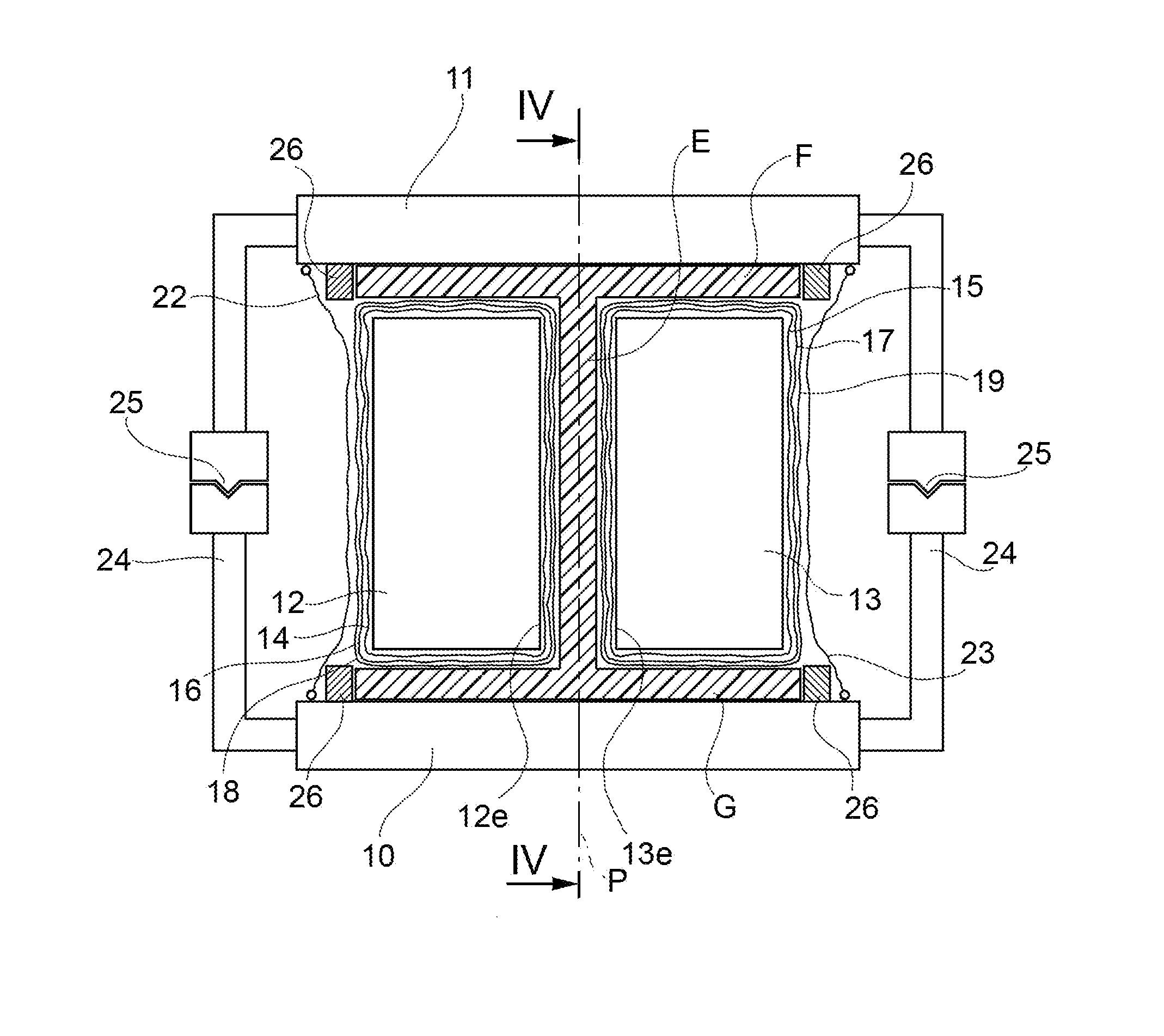
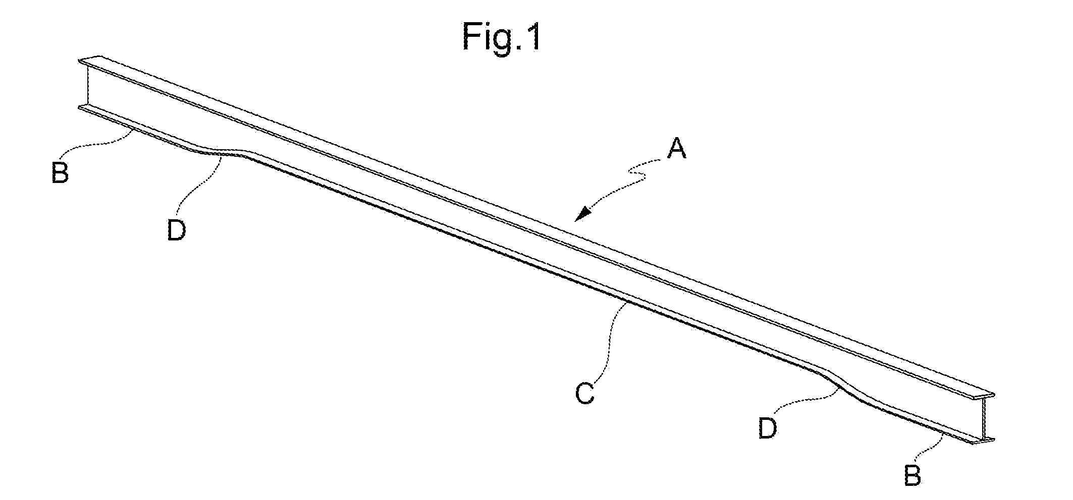
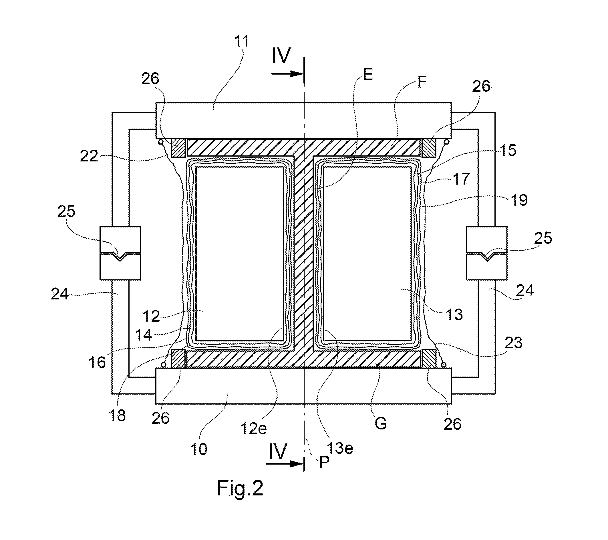
[0017]In order to manufacture a spar or beam A of composite material with an H-shaped cross section of the type shown in FIG. 1, it is first necessary to assemble the spar in the uncured state, using processes which are known and which are therefore not described in detail. These processes commonly include the lamination of plies preimpregnated with resin, followed by the thermoforming of two sectional elements with opposing C-shaped cross sections. A layer of adhesive is then applied along the joining area of each of the two sections, which are assembled by means of auxiliary tools, the two webs being brought together. Triangular-section fillers are then applied along the longitudinal recesses which are present in the areas of connection between the webs and flanges of the two sections, thus producing the H-section. The letters E, F and G (FIG. 2) indicate, respectively, the web, the upper flange and the lower flange of the beam A.

[0018]In the following description, reference is m...


PUM

PropertyMeasurementUnit
lengthaaaaaaaaaa
shapeaaaaaaaaaa
pressureaaaaaaaaaa

Abstract

A beam of fibre-reinforced curable thermosetting composite material is preliminarily assembled in an uncured condition. The beam is placed between two forming tools, namely a lower and an upper tool, shaped in such a way as to give the lower and upper flanges a predetermined shape, at least one of the flanges having a non-rectilinear profile viewed in a longitudinal vertical plane. Two longitudinally elongate rigid inserts are placed between the flanges at the sides of the web and are covered in respective airtight tubular bags. The spaces between the upper tool and the lower tool on the two opposite longitudinal sides are sealed. The open opposite ends of the tubular bags are also sealed in such a manner that the pressure applied in an autoclave during the step of curing causes the tubular bags to swell and presses them against the two opposite faces of the web and against the flanges of the beam. On completion of curing, the upper forming tool is removed and the inserts are extracted sideways.

Description

[0001]This application claims benefit of Serial No. TO2010A000175, filed 8 Mar. 2010 in Italy and which application is incorporated herein by reference. To the extent appropriate, a claim of priority is made to each of the above disclosed applications.[0002]The present invention relates to the field of aircraft construction in general and more specifically to a method for manufacturing beams of composite material, such as wing and empennage spars and fuselage beams, having an H-section which is variable along their length.BACKGROUND OF THE INVENTION[0003]In many applications, the spars or beams of an aircraft structure have an H-shaped cross section. For some specific applications, the height of the spar or beam varies in certain areas along its length, in such a way that the upper or lower flange has a non-rectilinear profile. More typically, the lower flange has to be raised in a given area, and consequently the web is locally shorter, while the shape and dimensions of the upper f...

Claims


Application Information

Patent Timeline
Patent Type & Authority Applications(United States)
IPC IPC(8): B29C70/30
CPCB29C70/44B29D99/0007B29K2105/246B29L2031/008Y10T156/1002B64C3/185B64C2001/0072Y02T50/433B64C1/065Y02T50/40
Inventor INSERRA IMPARATO, SABATOAVAGLIANO, LUIGICAPASSO, LUIGID'AGOSTINO, EMMANUELEDI TOMMASO, LUCAIAGULLI, GIANNI
Owner ALENIA AERONAUTICA SPA
Why Eureka
Try Eureka