Reflecting device with wide vision angle, reduced distortion and anamorphosis and reduced doubling of reflected images, particularly for vehicles

a wide-angle, reflected image technology, applied in the direction of optical viewing, instruments, transportation and packaging, etc., can solve the problems of collision with other vehicles, inability to correct in any way distortion, and wide blind spots

Inactive Publication Date: 2011-09-22
WIDE EYE
View PDF9 Cites 6 Cited by
  • Summary
  • Abstract
  • Description
  • Claims
  • Application Information

AI Technical Summary

Benefits of technology

[0026]The aim of the present invention is to eliminate the drawbacks noted above, providing a reflecting device, particularly for vehicles, that allows a wide field of vision both in the vertical extension of the field of vision and in a region located laterally to the vehicle on which it is installed, eliminating the so-called blind spot, offering a larger field of vision in the road surface cone at a distance from the mirror that is particularly useful in maneuvers from a stationary condition.

Problems solved by technology

In a spherical mirror, distortion in fact depends directly on the value of the radius of curvature; since the radius is chosen according to the dimensions of the mirror and to the field that must be viewed, it is not possible to correct in any way distortion, much less anamorphosis, i.e., the transformation to which an image is subjected when a geometric deformation occurs for which the ratio between the horizontal dimension and the vertical dimension is not constant.
The value of the minimum radius depends on the function performed by the mirror and on the directive itself; in any case, these reflecting devices, taking into account their usual dimensions, have a limited field of vision, approximately 20°, and accordingly have a rather wide blind spot, which often does not allow to show any approaching vehicles.
This is a danger factor and can induce the driver to perform maneuvers that are deemed safe on the basis of the images reflected by the device and instead can lead to collisions with other vehicles that cannot be seen by the driver if they have already entered the blind spot of the rear-view mirror.
These reflecting devices reduce the extent of the blind spot but are not free from drawbacks: the image of an overtaking car, when reflected at the transition between the main surface and the second surface, undergoes a sudden reduction in size and a consequent increase in distortion that is unpleasant for the driver.
Moreover, the apparent speed of the overtaking car also decreases greatly when the demarkation line between the two regions is crossed, and an evident and distinct discontinuity is also caused by the demarkation of the two surfaces and by the mandatory vertical dashed line.
All this can lead to errors in judging the distance and speed of the viewed vehicle, reckoning it to be more distant and slower than it actually is.
Another drawback that is particularly unpleasant depends on the fact that at the transition between the two portions of surfaces of a mirror, installed for example on the driver's side, the image that forms in the left eye is reflected in the main portion of the mirror while the image that is formed in the right eye is reflected in the secondary portion, which is strongly curved.
In conclusion, due to the steep gradient of the distortion and due to the reduction of the dimensions of the image that occurs at the transition, it is not possible to perceive distinctly a single image.
Not only is it unpleasant to see an image that is confused and not immediately identifiable, especially in conditions of less than optimum visibility, but this can also be dangerous, because it can make the driver dwell too long on the image produced by the rear-view mirror, in order to decipher it correctly, distracting him from controlling the vehicles that precede him.
For this reason, the eyes of the driver perceive two distinct images, which especially at night make the mirror unusable.
The mirror described in U.S. Pat. No. 7,025,469 therefore allows to increase the viewed field and to form an image with reduced distortion, but requires an antireflective treatment on the outer surface which increases production costs significantly.
This treatment in fact must have high efficiency, because it must be able to render invisible the lights of the headlights of cars during night driving; in view of the high intensity of the lights of headlights, a treatment with these characteristics is expensive to produce.

Method used


Image

  • Reflecting device with wide vision angle, reduced distortion and anamorphosis and reduced doubling of reflected images, particularly for vehicles
  • Reflecting device with wide vision angle, reduced distortion and anamorphosis and reduced doubling of reflected images, particularly for vehicles
  • Reflecting device with wide vision angle, reduced distortion and anamorphosis and reduced doubling of reflected images, particularly for vehicles

Examples


Embodiment Construction

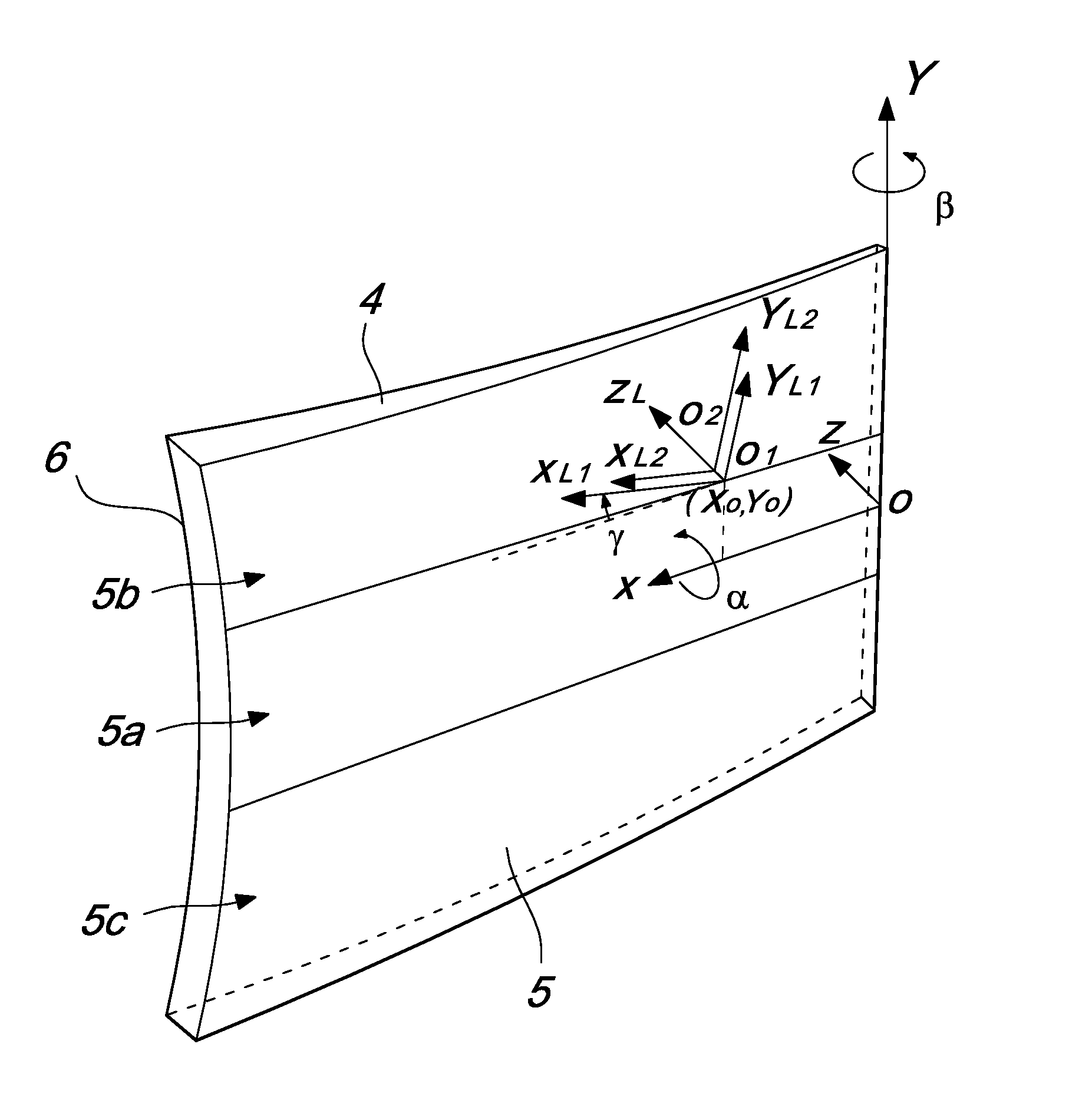
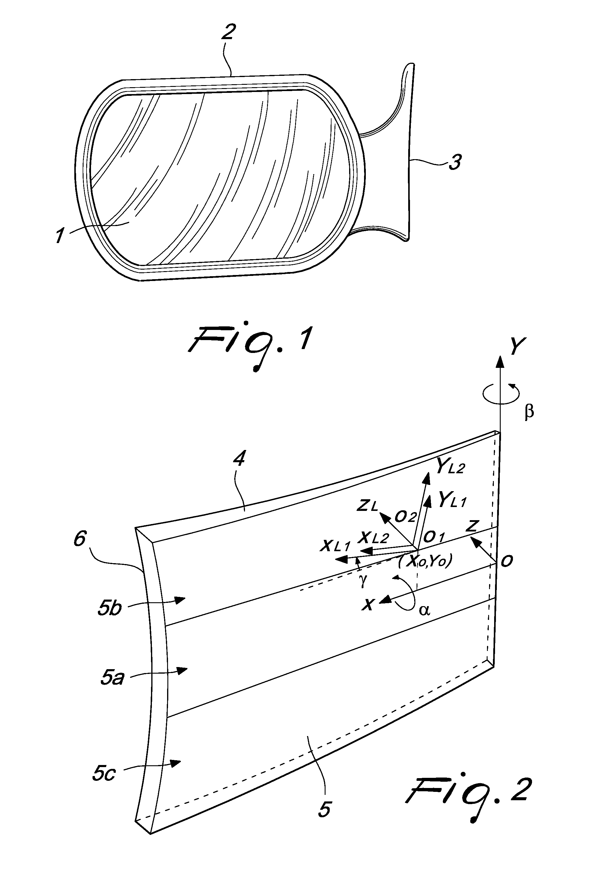
[0044]With reference to the figures, the reflecting device or rear-view mirror, generally designated by the reference numeral 1, comprises a frame 2 and a support 3 by means of which it is possible to install the reflecting device 1 on the car.

[0045]The reflecting device 1, which will be described hereinafter with reference to its main surfaces with an image reflection function, comprises a single monolithic body 4 made of transparent plastic material, such as for example thermoplastic materials with high-level light transmission such as Nylon, PMMA (polymethyl methacrylate) and polycarbonate, as well as thermosetting materials, such as for example CR39 (a polymer developed by the Columbia Chemical Co., located in Columbia, S.C., USA, which belongs to the class of polyesters). All the cited plastic materials ensure advantageous optical and mechanical properties with respect to glass, with the same refractive index and low chromatic dispersion but with a specific gravity equal to app...


PUM

PropertyMeasurementUnit
refractive indexaaaaaaaaaa
transparentaaaaaaaaaa
shape coefficientsaaaaaaaaaa

Abstract

A reflecting device with wide viewing angle, reduced distortion and anamorphosis and reduced doubling of reflected images, particularly for vehicles. The reflecting device has a monolithic body made of transparent plastic material and comprising an internal surface and an external surface, the latter facing the objects to be detected and being arranged opposite the internal surface. At least the external surface is constituted by an anamorphic surface which is non-revolution surface.

Description

TECHNICAL FIELD [0001]The present invention relates to a reflecting device with wide vision angle, reduced distortion and anamorphosis and reduced doubling of reflected images, used mainly as an external rear-view mirror for road and off-road vehicles.BACKGROUND ART[0002]External reflecting devices for road and off-road vehicles, known more commonly as rear-view mirrors, are mounted laterally on either sides of the vehicle and are constituted generally by a flat reflecting surface or by a convex spherical surface.[0003]The directives for type-approval of rear-view mirrors that are in force in the various countries, if they allow the use of convex reflecting surfaces (for example European directive 2003 / 97 / EC), set a minimum value of the radius of curvature in order to prevent the image generated by the device from being excessively small and having an excessively high level of distortion.[0004]In a spherical mirror, distortion in fact depends directly on the value of the radius of c...

Claims


Application Information

Patent Timeline
Patent Type & Authority Applications(United States)
IPC IPC(8): B60R1/08G01B11/22B23P11/00
CPCY10T29/49826B60R1/082
Inventor LOCATELLI, MARIOZUIN, ANDREA ENRICO
Owner WIDE EYE
Why Eureka
Try Eureka