Mascara brush with eyelash retaining member

a technology of eyelash retaining member and mascara brush, which is applied in the field of mascara brushes, can solve problems such as insufficient separation

Active Publication Date: 2011-09-22
GEKA
View PDF19 Cites 44 Cited by
  • Summary
  • Abstract
  • Description
  • Claims
  • Application Information

AI Technical Summary

Benefits of technology

[0024]This makes it more difficult for the eyelashes, once they have penetrated into the remaining free space between two bristle rows, to slip out again from this free space.

Problems solved by technology

However, the use of such massive bodies whose volume respectively exceed the volume of a single conventional bristle by several times also did not result in any decisive improvement, in particular also because the eyelashes are not distributed very well between these few large bodies which then constitute the bristle area, so that there is no sufficient separation.

Method used


Image

  • Mascara brush with eyelash retaining member
  • Mascara brush with eyelash retaining member
  • Mascara brush with eyelash retaining member

Examples


first exemplary embodiment

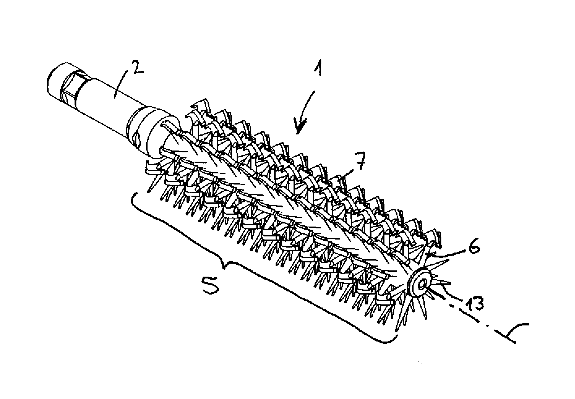
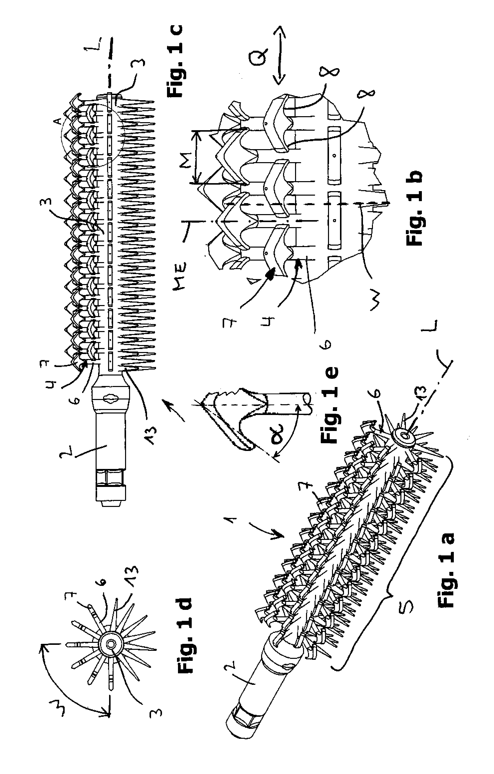
[0038]FIG. 1 shows a first exemplary embodiment of the invention.

[0039]The actual bristle body 1 of a mascara brush can be seen. The bristle body consists of a shoulder 2 for connecting the bristle body to the handle as well as of the rod-shaped bristle carrier 3. The bristle body forms a complete mascara brush only together with the shaft to be attached to the shoulder 2. The mascara brush of this exemplary embodiment has a pronounced longitudinal axis L, which at the same time constitutes the longitudinal axis of the bristle area. The bristle area can be called cylindrical or roller-shaped / conical (the latter is not shown herein).

[0040]The individual bristles 4 protrude in a substantially vertical direction from the bristle carrier 3 towards the outside and jointly form the bristle covering or bristle area 5. Their outermost end, which has the maximum distance from the bristle carrier 3, is referred to as the distal end. Their end forming the base area, with which they are attache...

second exemplary embodiment

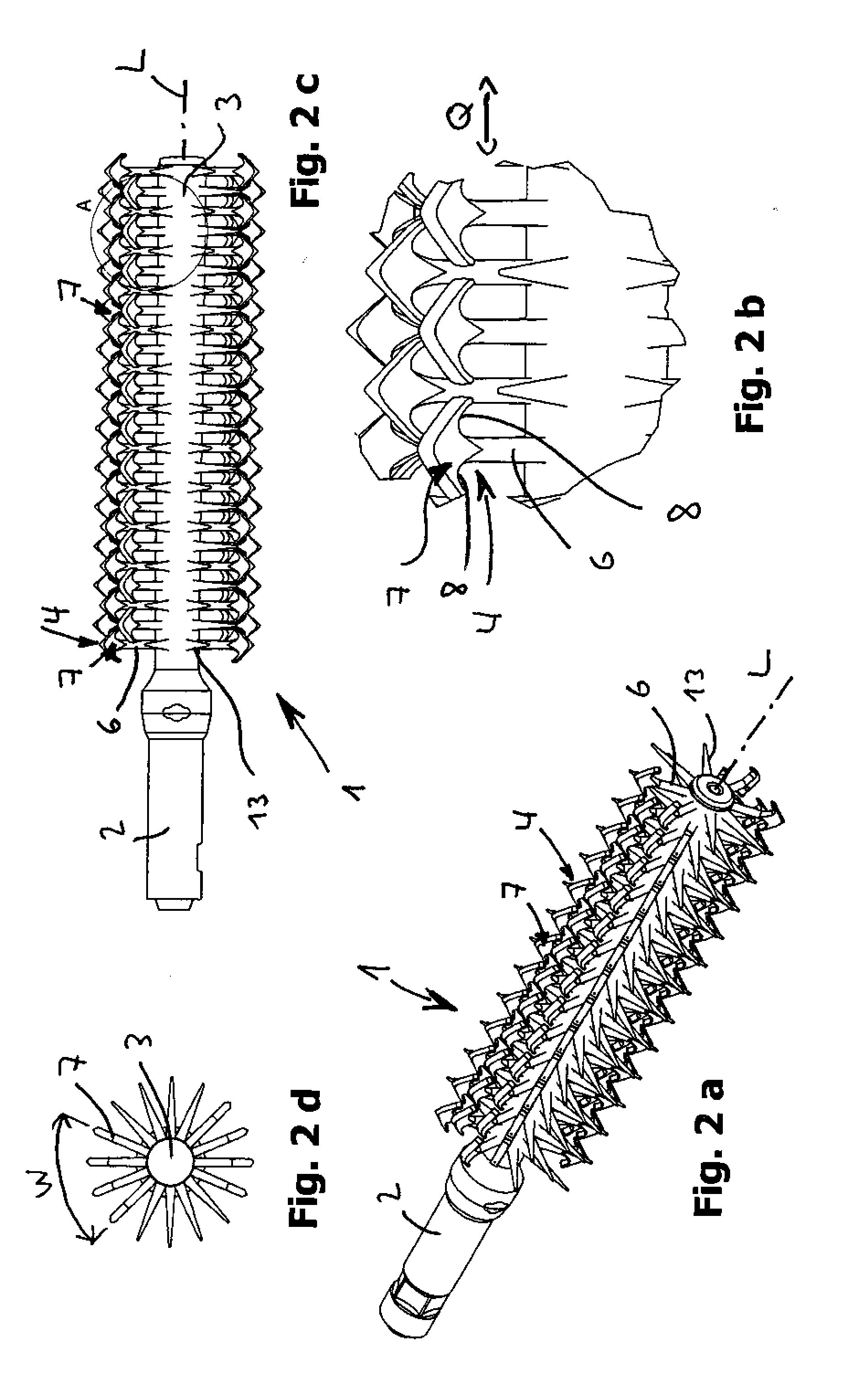
[0056]FIGS. 2a to 2d show a second exemplary embodiment which, with the exception of the following comments, completely corresponds to the first exemplary embodiment, so that the statements at the beginning apply here mutatis mutandis.

[0057]The two exemplary embodiments differ in the distance that the individual rows of the bristles equipped with the eyelash retaining organ 7 have. While four rows of bristles with eyelash retaining organs disposed one behind the other in the longitudinal direction “cover” an angle W of 90° in the first exemplary embodiment, four such rows, in the second exemplary embodiment, only cover an angle of 60°. In exchange, however, two opposite sections of the bristle area are provided with such bristles that comprise eyelash retaining organs, instead of with conventional bristles.

third exemplary embodiment

[0058]FIGS. 3a to 3d disclose a third exemplary embodiment. With regard to its function, this third exemplary embodiment substantially corresponds to the first two exemplary embodiments mentioned, so that the statements pertaining thereto also apply to this exemplary embodiment to the extent that the comments below do not specify otherwise.

[0059]The essential difference to the two first exemplary embodiments is that, in this exemplary embodiment, the two hook-like appendages 8 are designed such that they can be elastically bent towards the lateral end of the bristle with relative ease, whereas in the case of being bent in the distal direction, they still offer a sufficiently large resistance so that their function as an eyelash retaining organ 7 is not challenged.

[0060]In this case, no specific instructions as to dimensions can be given here, since the dimensioning required for achieving the desired effect is very strongly dependent upon the individual case, namely on the geometry a...


PUM


Abstract

The invention relates to a mascara brush comprising a carrier portion and a bristle covering of bristles respectively protruding outwardly along their longitudinal bristle axis L from the carrier portion, wherein the bristle covering comprises bristles consisting essentially of a bristle stem and an eyelash retaining organ adjoining thereto, which is configured as a retaining projection which projects over the surface of the bristle stem located, viewed in the direction of the longitudinal bristle axis, proximally-below it, in a direction transverse to the direction of the longitudinal bristle axis, or which is configured as a retaining groove open towards the distal end in the end face of the distal end of a bristle.

Description

CROSS REFERENCE TO RELATED APPLICATIONS[0001]This application claims the benefit of U.S. Provisional Application No. 61 / 314,453 filed Mar. 16, 2010.FIELD OF THE INVENTION[0002]The invention relates to a mascara brush for applying mascara onto the eyelashes.BACKGROUND OF THE INVENTION[0003]Such brushes are subject to a variety of requirements. Not only are they supposed to be capable of applying mascara as efficiently as possible, that is, in one stroke, if possible, without having to dip the mascara brush several times. Rather, they are also supposed to make it possible to curve the eyelashes in the sense of an upward curve (at the upper eyelid) or a downward curve (at the lower eyelid)—a treatment of the eyelashes referred to as “curling”.[0004]Moreover, they are also supposed to be capable of exerting certain tensile forces on the eyelashes so that they are visually extended, which is also referred to by the term “extending / lengthening”.[0005]Countless variations of mascara brushe...

Claims


Application Information

Patent Timeline
Patent Type & Authority Applications(United States)
IPC IPC(8): A45D40/26A46B11/00
CPCA45D40/262A46B9/021A46D1/0292A46D1/0284A46D1/00
Inventor KULIK, DANIELA
Owner GEKA
Why Eureka
Try Eureka