Method for controlling the process when producing a paving mat and road finisher

a technology for paving mats and finishers, which is applied in the direction of paving details, roads, constructions, etc., can solve the problems of inability to direct process control, and inability to control the process directly

Active Publication Date: 2011-09-22
JOSEPH VOEGELE AG
View PDF12 Cites 9 Cited by
  • Summary
  • Abstract
  • Description
  • Claims
  • Application Information

AI Technical Summary

Problems solved by technology

Here too no direct process control is possible, because the setting angle of the screed or a change of the setting angle occurring during laying is not taken into account.
A direct process control is not possible with this method.

Method used


Image

  • Method for controlling the process when producing a paving mat and road finisher
  • Method for controlling the process when producing a paving mat and road finisher
  • Method for controlling the process when producing a paving mat and road finisher

Examples


Embodiment Construction

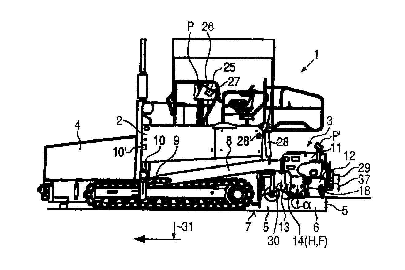
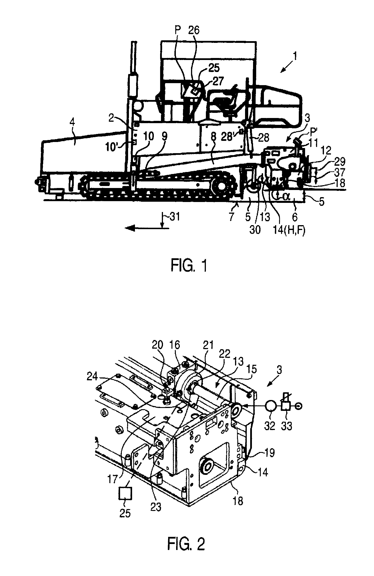
[0034]FIG. 1 shows a self-propelled road finisher 1 carrying out a laying process, i.e. during the laying of a layer 6 of bituminous or concrete paving material 5 on a level surface 7 with a paving thickness S and a laying rate V relative to the level formation 7, whereby the layer 6 is at least pre-compacted by a pre-compaction system 13 of a screed 3 and laid flat.

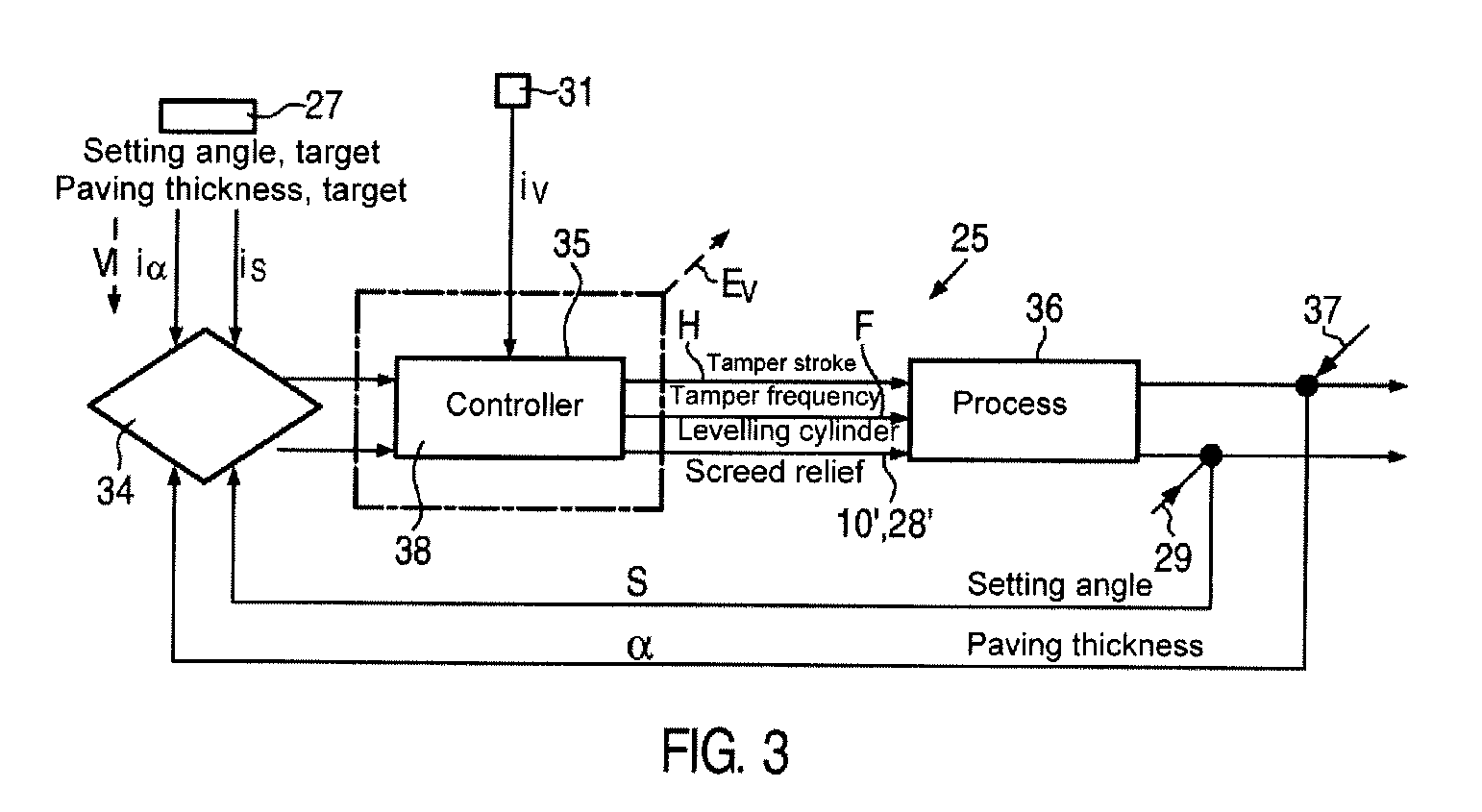
[0035]The core of the road finisher 1 is a computerized, either fully automatic or operator assisted closed-loop control system 25, for example in an operating console P in a driver's cab and / or in an external control position P′ on the screed 3. The closed-loop control system 25 can be used by an operator such that the operator can directly control the laying process and essentially needs to select no laying parameters himself and / or change them when laying.

[0036]On the chassis 2 of the road finisher 1 a bunker 4 is arranged at the front, from which a longitudinal conveyor system, which is not highlighted, deposits pavi...


PUM


Abstract

A method for controlling the process laying a layer in a selectable paving thickness with a road finisher in which the laying process is automatically controlled in that a target value for the paving thickness is entered into an automatic closed-loop control system and communicates the actuating signals to such members and the signals. A road finisher has a computerized, either fully automatic or operator aided closed-loop control system for the direct control of the laying process with control of the paving thickness to a predetermined target value and for the optimization of the operating point of the pre-compaction system, which is connected to sensors at least for the acquisition of the setting angle of the screed, of the paving thickness and of the laying rate.

Description

FIELD OF THE INVENTION[0001]The invention relates to a method of controlling the process of laying a layer of bituminous or concrete paving material in a selectable paving thickness on a level surface with a road finisher and a road finisher for practicing the method.BACKGROUND OF THE INVENTION[0002]German patent DE 198 36 269 A describes a method in which the tamper frequency is controlled according to a predetermined relationship dependent on the sampled setting angle of the screed. Since only the setting angle is considered as the influencing variable, the operator must adjust further influencing variables according to his own judgement, i.e. the operator cannot directly control the laying process, but rather must himself select certain machine parameters, whereby he is supported by the closed-loop control of the tamper frequency in dependence of the setting angle. It is the operator's responsibility to select the machine parameters to be entered such that he ultimately achieves ...

Claims


Application Information

Patent Timeline
Patent Type & Authority Applications(United States)
IPC IPC(8): E01C11/00E01C19/38
CPCE01C19/4853E01C19/002
Inventor BUSCHMANN, MARTINWEISER, RALFEUL, ACHIM
Owner JOSEPH VOEGELE AG
Why Eureka
Try Eureka