Casting, molding or pressing tool with temperature control medium channels

a technology of molding or pressing tools and temperature control medium, which is applied in the direction of dough shaping, manufacturing tools, applications, etc., can solve the problems of increasing the cooling requirement, the inability to meet the requirements of injection molding tools with heatable tool inserts, and the production of considerable mechanical and thermal stresses, etc., to achieve rapid and uniform cooling, increase the productivity of injection molding, and the effect of increasing the productivity

Inactive Publication Date: 2011-09-22
LINDE AG
View PDF1 Cites 8 Cited by
  • Summary
  • Abstract
  • Description
  • Claims
  • Application Information

AI Technical Summary

Benefits of technology

[0015]The thermal spraying methods described result in significantly improved properties of coatings and materials. The products thus produced have a high wear resistance and corrosion resistance. By a choice of suitable components it is possible to achieve a particularly good thermal and / or electrical conductivity and / or particularly advantageous expansion characteristics of corresponding components.
[0032]By the use of such apparatus and processes it is possible to achieve a significant increase in the productivity of injection molding and die stamping processes as it enables rapid and uniform cooling (and optionally also heating) of the injected material in the mold. The length of time until an injection molded or die-stamped component can be demolded is hereby significantly reduced, with the result that the cycle time of a corresponding apparatus can be reduced.

Problems solved by technology

Before a workpiece produced by injection molding can be demolded, however, it must have fallen below the demolding temperature at every point, as otherwise undesirable deformation could occur as a result of and subsequent to the demolding.
However it is precisely in these regions that there is an increased cooling requirement.
The general requirement when producing injection molding tools, according to which specific distances have to be maintained between the temperature control medium channels relative to one another and to the surface of the cavity, cannot therefore always be met in injection molding tools with heatable tool inserts.
A general problem with heated and subsequently cooled components is the considerable mechanical and thermal stresses which are produced for example by different thermal expansion co-efficients.
Where there are very great temperature differences, such as may occur for example when using carbon dioxide cooling, these problems are significantly intensified.
In particular, disadvantages of this kind occur in heating elements of a sandwich structure.
Both requirements significantly increase the production costs of corresponding heating systems.

Method used


Image

  • Casting, molding or pressing tool with temperature control medium channels
  • Casting, molding or pressing tool with temperature control medium channels
  • Casting, molding or pressing tool with temperature control medium channels

Examples


Embodiment Construction

[0036]In the drawings, identical or similar elements are shown with identical reference numerals. The associated description is not repeated, in the interests of clarity.

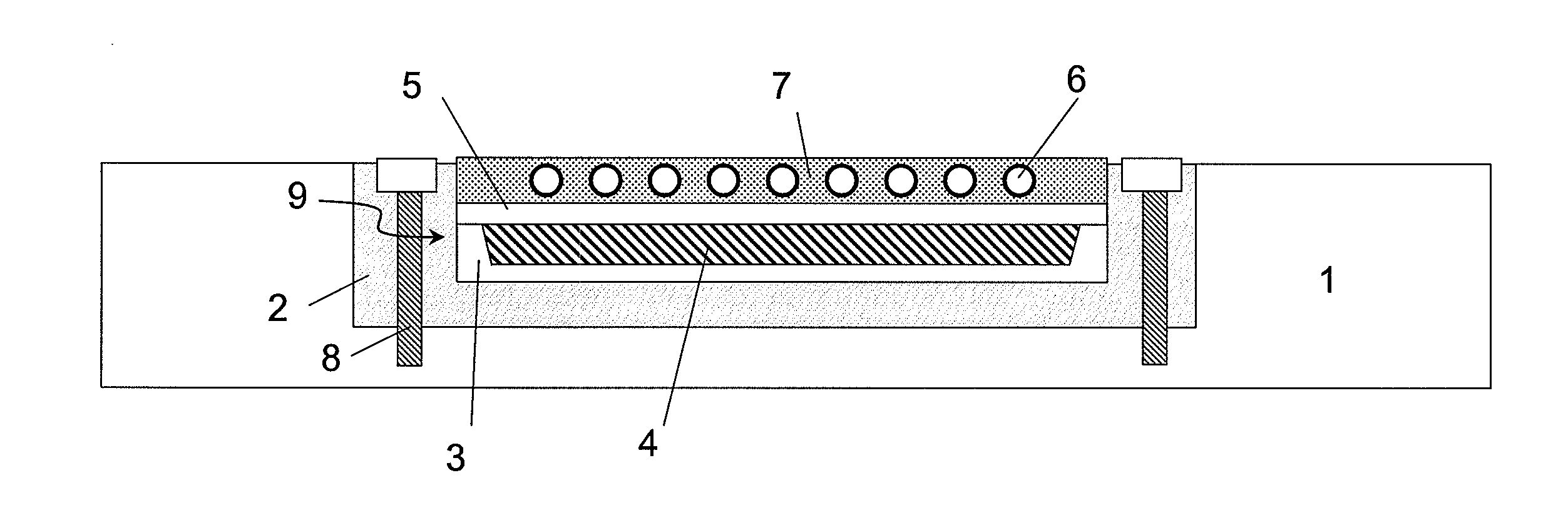
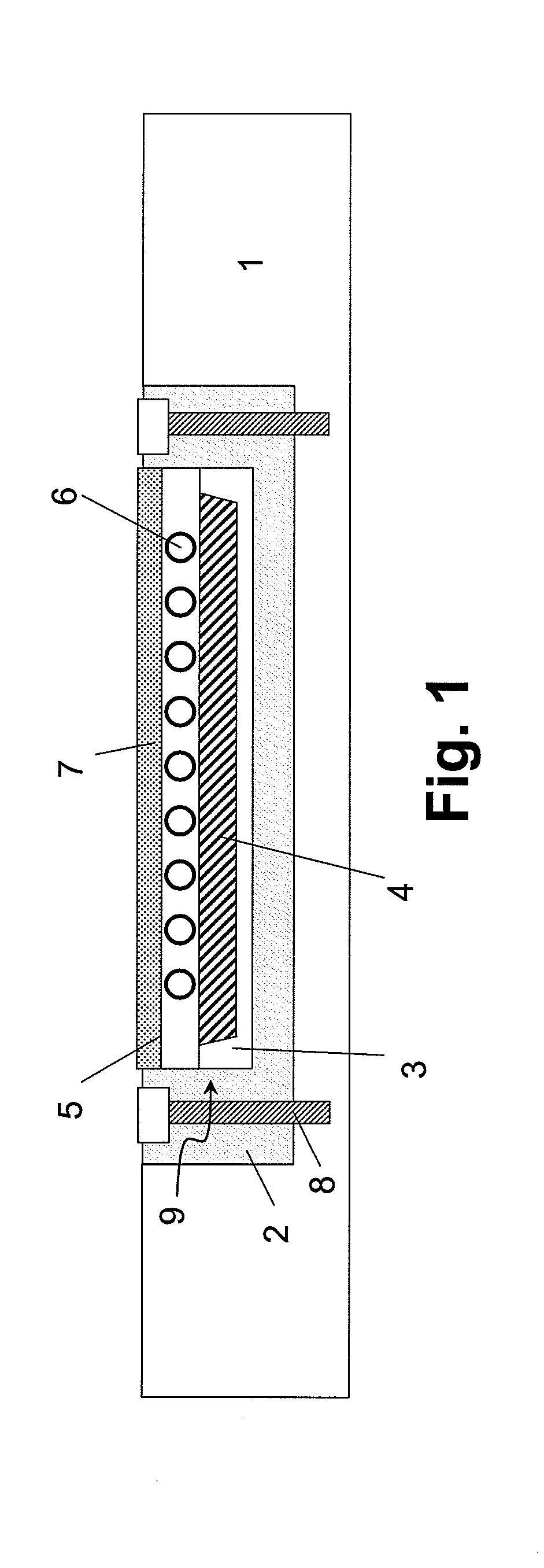
[0037]FIG. 1 schematically shows a part of a casting, molding or pressing tool 1 of a pressing or injection apparatus. The tool 1 comprises a tool insert 2 which is attached to the tool 1 by screws 8. The tool insert 2 has a layered structure 9 which will be explained hereinafter.

[0038]The layer structure 9 has an insulating material 3 on the substrate side. The insulating material 3 which is pulled upwards at its side edges to ensure lateral insulation is advantageously applied by a spraying process or placed in a tool insert. Advantageously a ceramic material is used for the insulating layer 3. A heating layer 4, for example an electro resistive or inductive heater 4, is provided on the insulating layer 3, by spraying or by some other method. The heating layer 4 may comprise electrical connections (not shown) whic...


PUM

PropertyMeasurementUnit
temperatureaaaaaaaaaa
insulatingaaaaaaaaaa
viscosityaaaaaaaaaa

Abstract

In a method of producing a casting, molding or pressing tool (1) or tool insert (2) with at least one material layer (3, 5, 7) and with temperature control medium channels (6) arranged in the at least one material layer (3, 5, 7), the temperature control medium channels (6) are introduced into the at least one material layer (3, 5, 7) using a thermal spray process (2).

Description

CROSS REFERENCE TO RELATED APPLICATIONS[0001]This application claims priority of the German patent application 10 2010 003 033.3 filed Mar. 18, 2010 which is incorporated by reference herein.FIELD OF THE INVENTION[0002]The present invention relates to a method of producing a casting, molding or pressing tool or a corresponding tool insert having at least one material layer and having temperature control medium channels arranged in the at least one material layer, a correspondingly produced casting, molding or pressing tool or a correspondingly produced tool insert, a material layer of a tool or tool insert of this kind, and a casting, molding or pressing process using a tool or tool insert of this kind.[0003]Although the present invention is described hereinafter predominantly with respect to the injection molding of plastics parts, it is not restricted to this but can be used in a variety of pressing, casting or molding processes, for example in the light metal die casting of alumi...

Claims


Application Information

Patent Timeline
Patent Type & Authority Applications(United States)
IPC IPC(8): B29C33/02B29C35/00C23C4/00B29C39/38
CPCB22D17/2218B29C33/02B29C33/046C23C24/04B29C2045/7393C23C4/02C23C4/185B29C45/7337
Inventor KROMMER, WERNERHENINGER, ROLFKURTEN, ANDREASPETERS, GUIDOPRALLER, ANDREAS
Owner LINDE AG
Why Eureka
Try Eureka