Insufflation of body cavities

a body cavity and insufflation technology, applied in the field of insufflation of body cavities, can solve the problems of patient heat loss, insufflation gas conditioning system, and post-surgical pain and significant complications, and achieve the effect of reducing the number of patients

Inactive Publication Date: 2011-09-22
AEROSURGICAL
View PDF0 Cites 39 Cited by
  • Summary
  • Abstract
  • Description
  • Claims
  • Application Information

AI Technical Summary

Benefits of technology

[0008]According to the invention there is provided a connector for an insufflation system comprising a housing having a mixing chamber, an insufflator gas inlet to the mixing chamber, an aerosolised liquid inlet to the mixing chamber, an outlet for delivery of insufflation gas with aerosolised liquid entrained therein, the connector causing a substantial reduction in the velocity of insufflation gas from the insufflation gas inlet as it enters the mixing chamber and causing an increase in the velocity of the insufflation gas with entrained aerosol between the mixing chamber and the outlet.

Problems solved by technology

Gas such as carbon dioxide that is used for insufflation is both cold and dry and it is not surprising therefore those patients undergoing laparoscopic procedures often suffer a significant drop in core body temperature, which can result in considerable post-surgical pain and significant complications, such as cardiac stress, immunological and clotting problems, for the patient.
By using standard thermo physical principles it has been shown that the major cause of patient heat loss is due to evaporation from the body acting to humidify the large volumes of dry insufflated gas at ATPD (Ambient Temperature Pressure Dry) passing into the body which is at BTPS (Body Temperature Pressure Saturated).
However in general, known insufflation gas conditioning systems suffer from one or more disadvantages including complexity of construction involving expensive monitoring devices, inaccurate control and / or difficulties in using them in a controlled working environment.
These operate directly in the flow path of the insufflation gas and are therefore inherently susceptible to affecting pressure or flow, dependent upon their level of saturation and condition.
Other prior art devices require the cumbersome procedure of passing gas over and through non-heated or heated liquid containers.
Such devices present the major drawback of impeding pressure measurement in the insufflation cavity.
Systems using conventional jet nebulisers or nebulisation catheters exhibit one or more of the following disadvantages: impaction of larger particles resulting in poor dispersion of aerosol and diminished dose, fogging in the body cavity thus reducing the surgeon's visibility, interference with insufflator settings increasing flow / pressure in the system.

Method used


Image

  • Insufflation of body cavities
  • Insufflation of body cavities
  • Insufflation of body cavities

Examples


Embodiment Construction

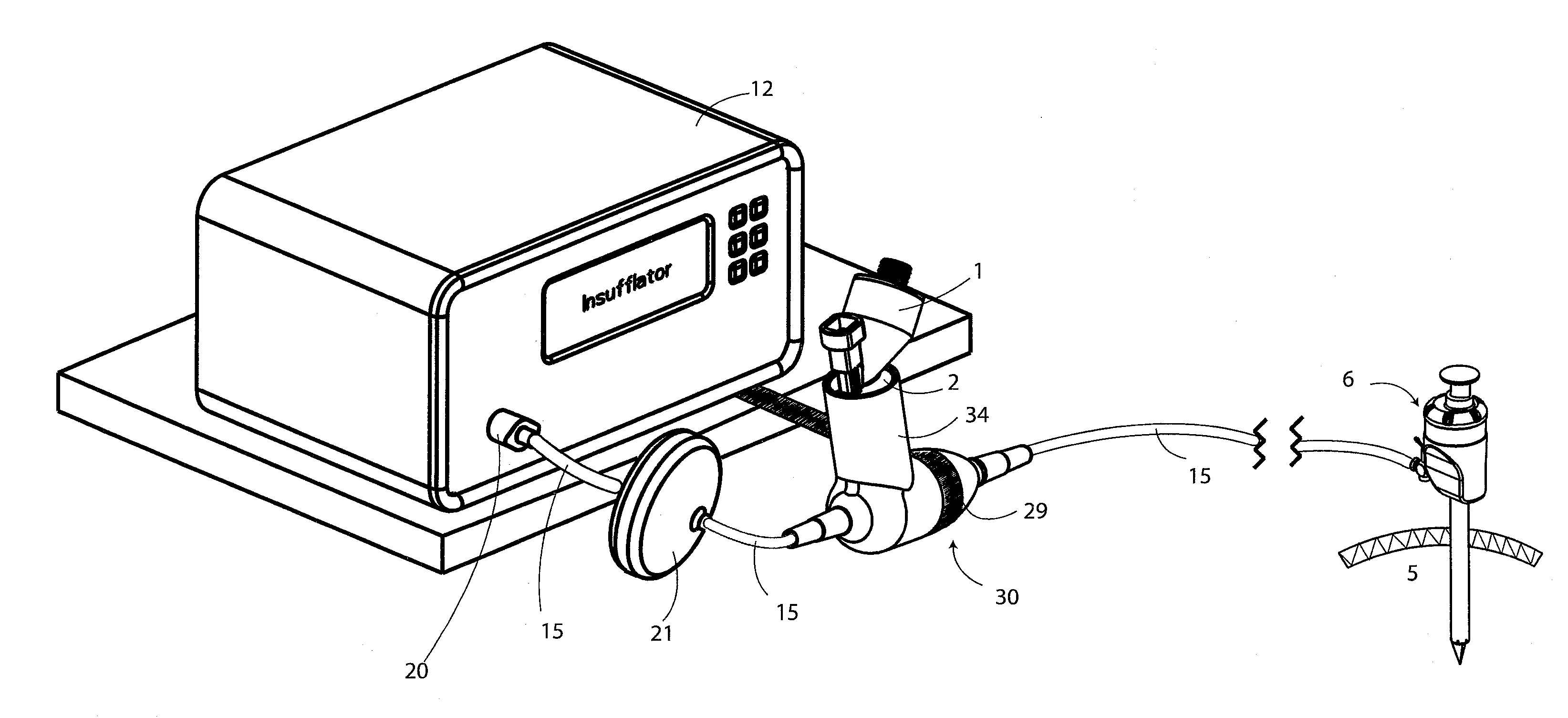
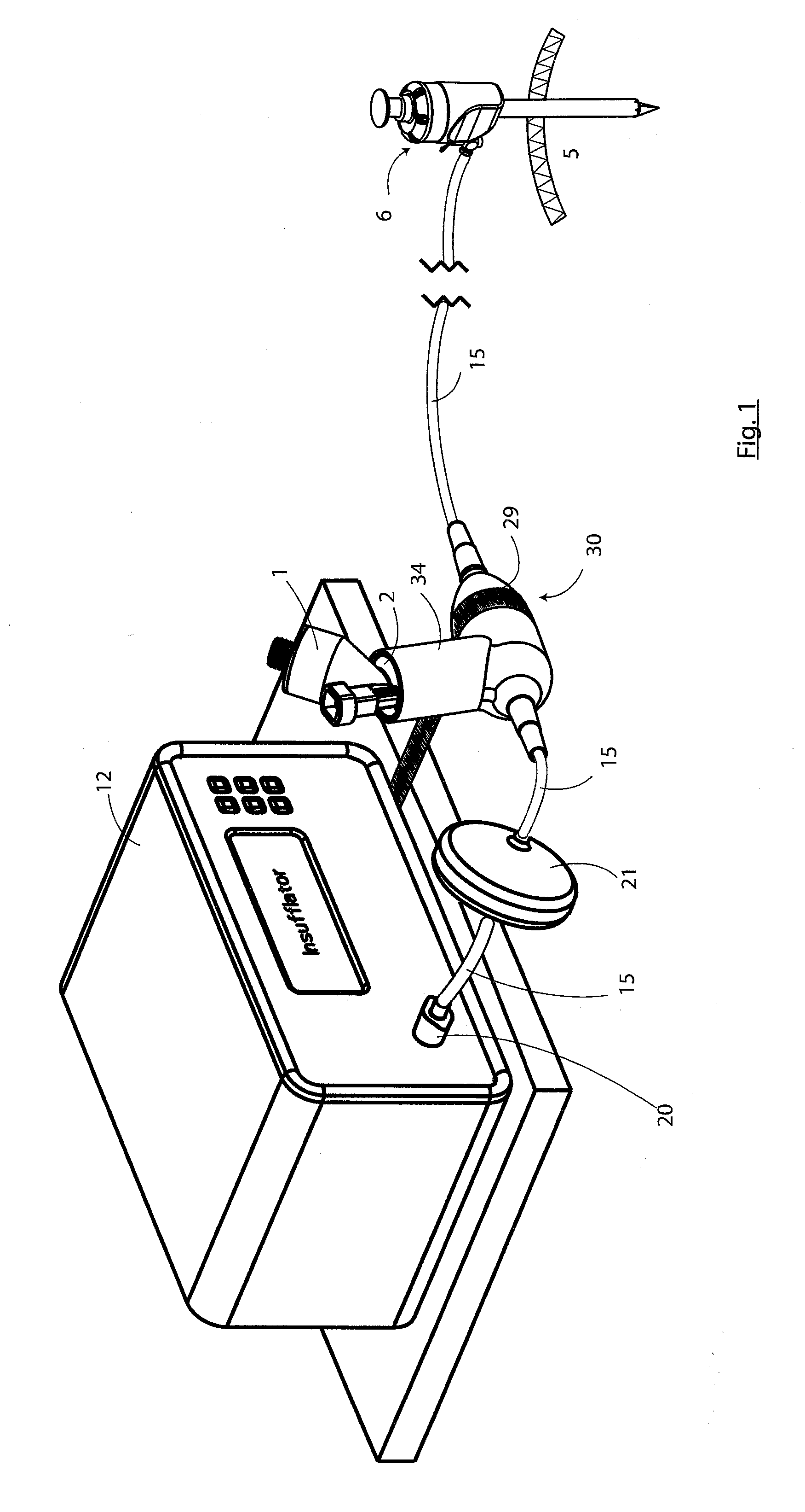
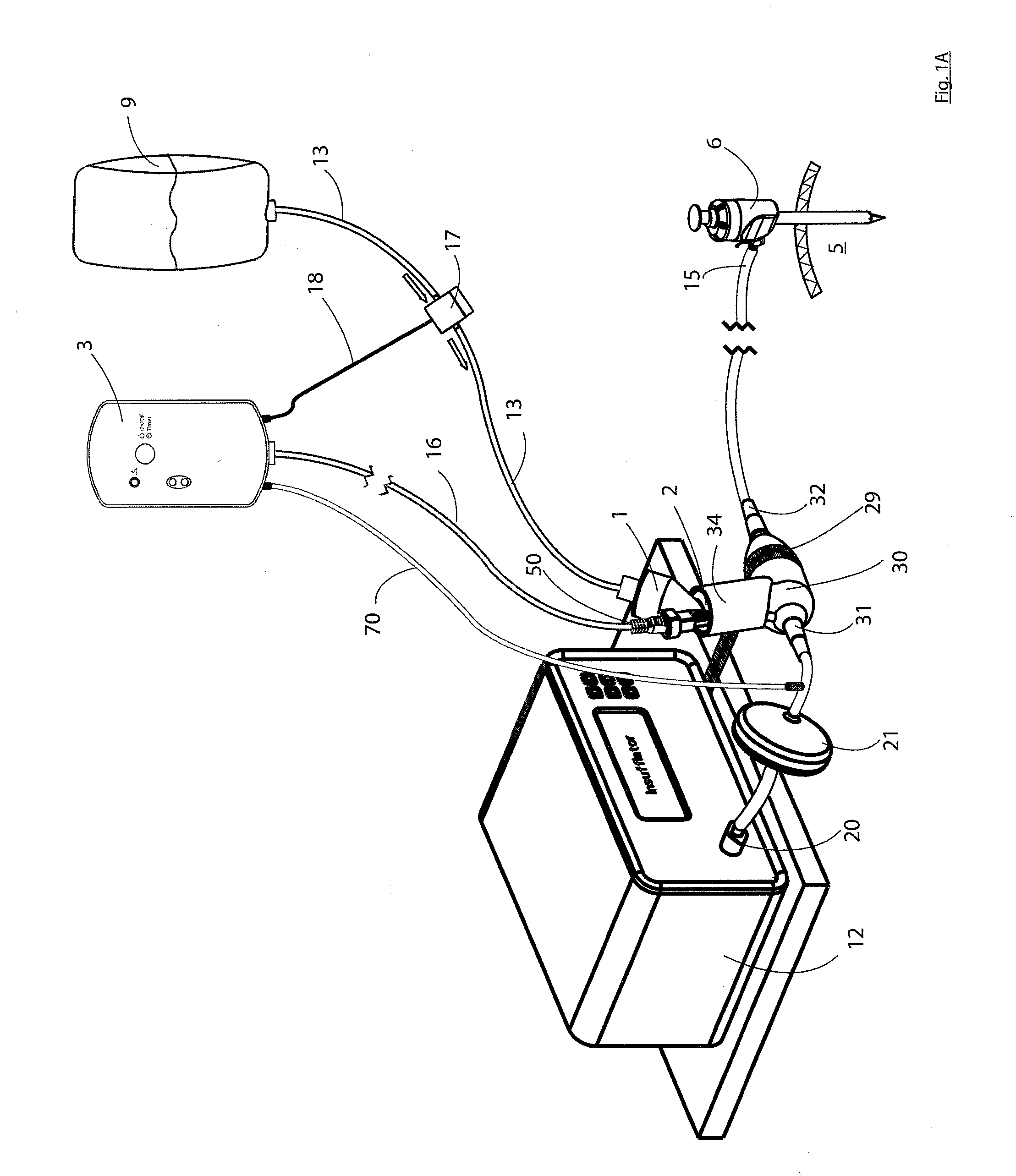
[0082]Referring to FIG. 1 there is illustrated an apparatus according to the invention for use in insufflation of a body cavity 5, in this case through a trocar 6. One such application is laparoscopic surgery. The device is also suitable for use in any situation involving insufflation of a body cavity such as in arthroscopies, pleural cavity insufflation (for example during thoracoscopy), retroperitoneal insufflations (for example retroperitoneoscopy), during hernia repair, during mediastinoscopy and any other such procedure involving insufflation.

[0083]The apparatus comprises a reservoir 1 for storing an liquid solution, an aerosol generator 2 for aerosolising the solution, and a controller 3 for controlling operation of the aerosol generator 2. In the invention aerosolised liquid solution is entrained with insufflation gas. The gas is any suitable insufflation gas such as carbon dioxide. Other examples of suitable insufflation gases are nitrogen, helium and xenon.

[0084]The insuffl...


PUM


Abstract

An apparatus for use in insufflation of a body cavity 5, such as through a trocar 6 is described. One such application is laparoscopic surgery. The device is also suitable for use in any situation involving insufflation of a body cavity such as in arthroscopies, pleural cavity insufflation (for example during thoracoscopy), retroperitoneal insufflations (for example retroperitoneoscopy), during hernia repair, during mediastinoscopy and any other such procedure involving insufflation. The apparatus comprises a reservoir 1 for storing an liquid solution, an aerosol generator 2 for aerosolising the solution, and a controller 3 for controlling operation of the aerosol generator 2. Aerosolised liquid solution (which main contain a pharmaceutical) is entrained with insufflation gas using a T-piece connector or housing 30 having an insufflation gas inlet 31 and an outlet 32. The connector 30 also comprises an aerosol supply conduit 34 for delivering the aerosol from the aerosol generator 2 into a mixing chamber 33 in which the aerosol is entrained with insufflation gas. The aerosol insufflation gas mixture passes out of the connector 30 through the outlet 32 and is delivered along the insufflation gas conduit 15 to the trocar 6 for delivery into a body cavity 5. The connector 30 causes a substantial sudden reduction in the velocity of the insufflation gas from the insufflation gas inlet as it enters the mixing chamber 33. The connector 30 also causes a gradual increase in the velocity of the insufflation gas with entrained aerosol between the mixing chamber 33 and the outlet 32.

Description

CROSS-REFERENCE TO RELATED APPLICATIONS[0001]The present application claims the benefit of U.S. Provisional Patent Application No. 61 / 315,125, filed Mar. 18, 2010, the entire contents of which are incorporated herein by reference.BACKGROUND OF THE INVENTION[0002]Laparoscopic surgery, also called minimally or less invasive surgery (MIS or LIS) or keyhole surgery is a modern surgical technique in which operations in the body are performed through small incisions as compared to the larger incisions needed in traditional surgical procedures. Gas such as carbon dioxide is delivered, via an insufflator, into a body cavity such as the abdomen leading to the formation of a pneumoperitoneum, thereby providing sufficient space for the surgeon to operate. The insufflator maintains the pneumoperitoneum and acts to renew the gas when leaks occur.[0003]Gas such as carbon dioxide that is used for insufflation is both cold and dry and it is not surprising therefore those patients undergoing laparos...

Claims


Application Information

Patent Timeline
Patent Type & Authority Applications(United States)
IPC IPC(8): A61M13/00
CPCA61M11/005A61M13/00A61M16/0816A61M19/00B05B17/0646A61M2202/048A61M2205/3331A61M2205/7518B05B12/081A61M2202/0468A61M16/0833
Inventor LILLIS, CLAIRE ELIZABETHDUFFY, CONOR PAULPOWER, PATRICK JOSEPH
Owner AEROSURGICAL
Why Eureka
Try Eureka