In-Wall Hydronic Thermal Control System and Installation Method

a hydronic thermal control system and hydronic thermal control technology, applied in the direction of laminated elements, lighting and heating apparatus, heating types, etc., can solve the problems of limited success in incorporating hydronic thermal control systems in vertically-extending walls of buildings, mechanical instability of wallboards, and subject to breakage, etc., to achieve stable incorporation of tubing and good thermal conductivity

Active Publication Date: 2011-09-29
FIEDRICH JOACHIM
View PDF21 Cites 2 Cited by
  • Summary
  • Abstract
  • Description
  • Claims
  • Application Information

AI Technical Summary

Benefits of technology

[0014]The present invention concerns an improved system for installing tubing of hydronic thermal control systems in the walls of buildings. It allows for the stable incorporation of the tubing in the walls while ensuring good thermal conductivity between the tubing and the building's room.

Problems solved by technology

In the past, there has been limited success at incorporating hydronic thermal control systems in the vertically-extending walls of buildings.
The previous approach of incorporating the tubing in the gypsum wallboard met with limited success.
Incorporation of the tubing in the wallboard and / or the formation of tracks in the wallboard made the wallboard mechanically unstable and subject to breakage.
Moreover, the relatively weak gypsum material did not hold the relatively rigid and inflexible PEX (cross-linked polyethylene) tubing that is commonly used for hydronic thermal management systems.
Moreover, often rugs are used on the floors, which undermine the ability of the tubing installed in the floors to control the temperature of the associated room.

Method used


Image

  • In-Wall Hydronic Thermal Control System and Installation Method
  • In-Wall Hydronic Thermal Control System and Installation Method
  • In-Wall Hydronic Thermal Control System and Installation Method

Examples


Embodiment Construction

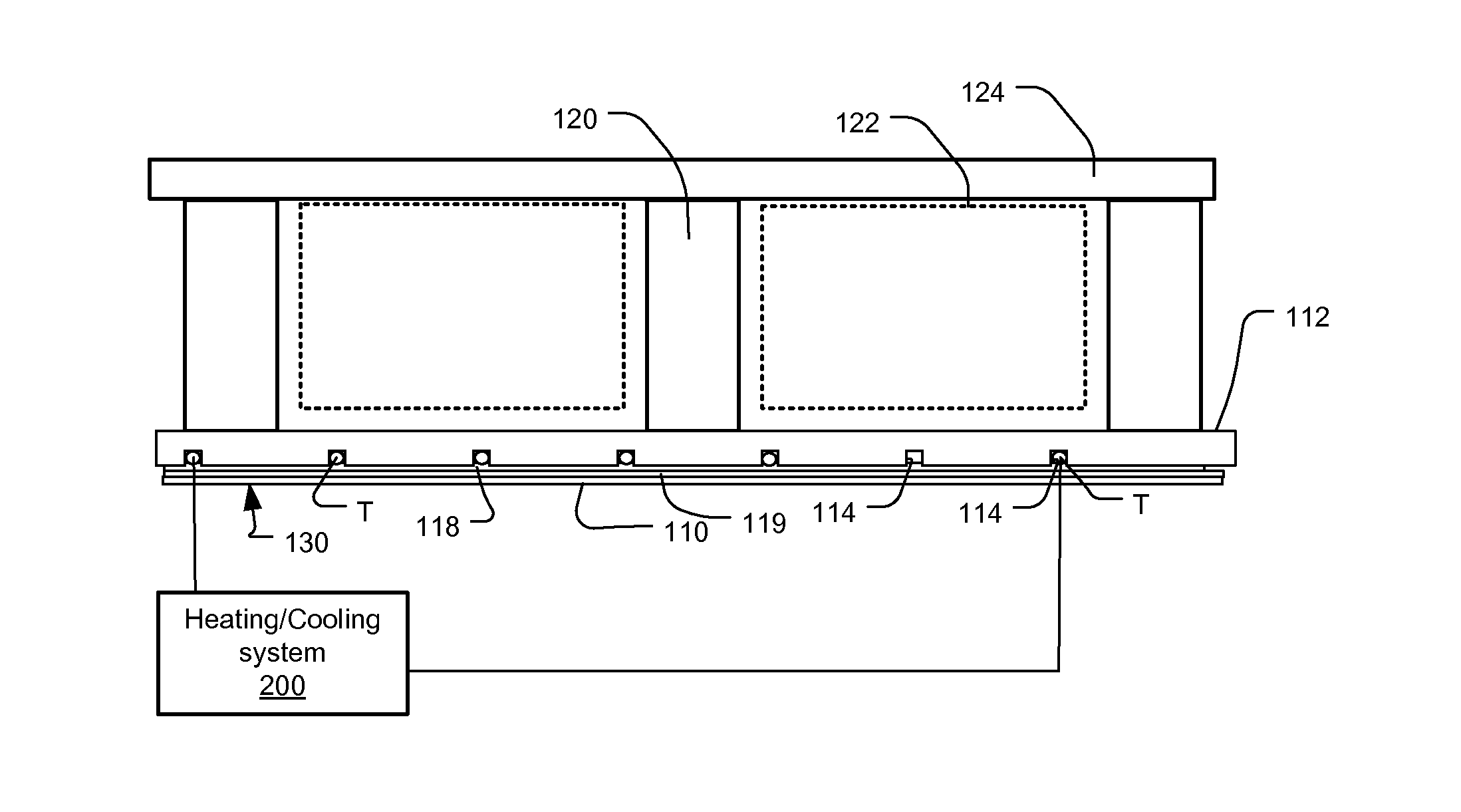
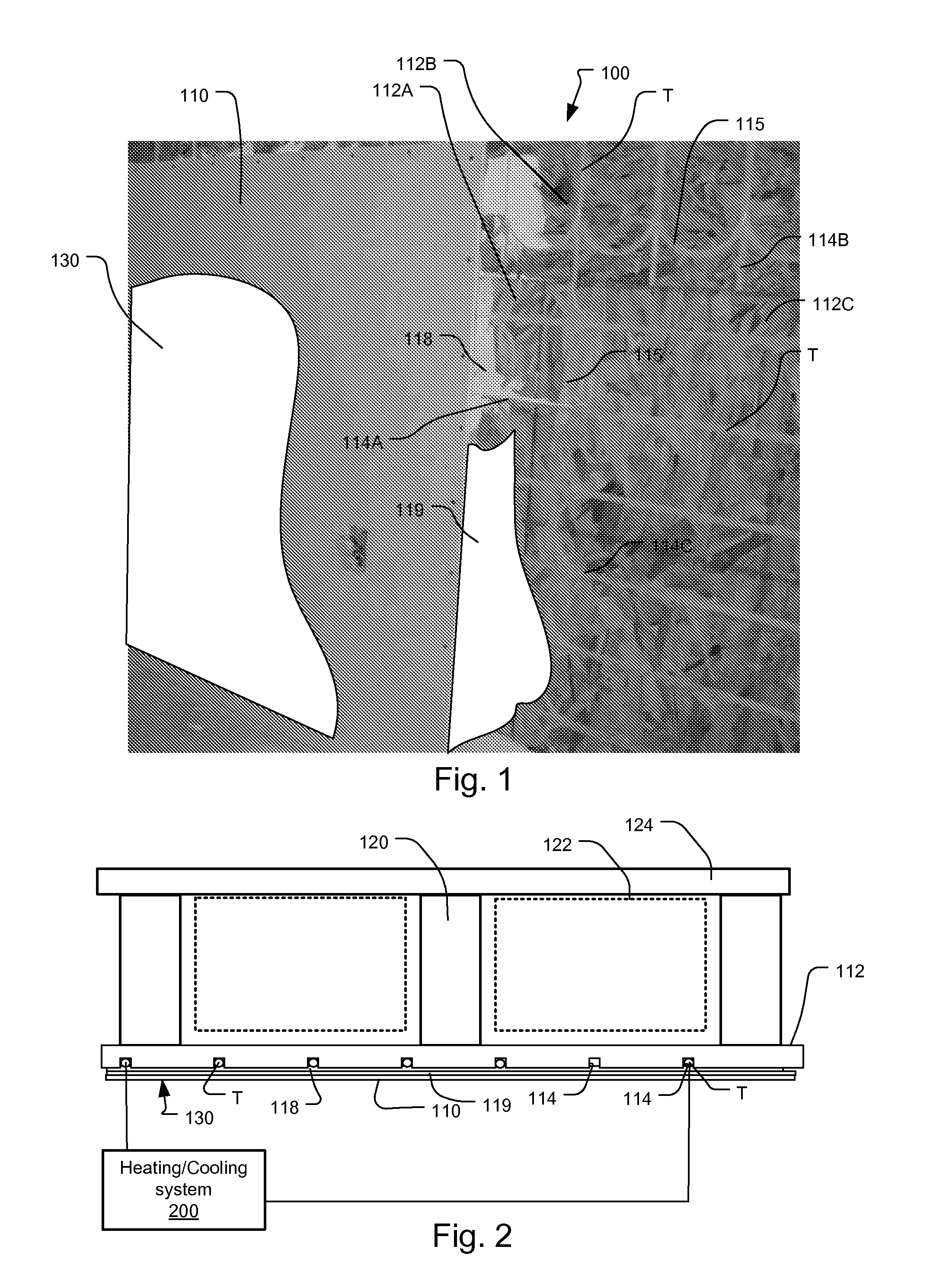
[0022]FIG. 1 shows a wall including a hydronic thermal management system, which has been constructed according to the principles of the present invention.

[0023]The wall 100 is constructed from tubing panels 112, i.e., 112A, 112B, 112C. In the preferred embodiment, these tubing panels 112 are constructed from a wood material. In one example, the panels are plywood panels. In one implementation, the tubing panels 112 are fabricated from oriented strand board (OSD) plywood, which is produced by binding wood chips with a mix of glue and resin. In another example, the panels 112 are constructed from CDX plywood. This type of plywood is produced by gluing together sheets of veneer, each layer being glued in the opposite grain to the one below it. In still other examples, other engineered wood or plant material products are used for the tubing panels 112. These include fiberboard, such as particle board, and hard board.

[0024]In the current implementation, the thickness of the tubing panels...


PUM


Abstract

A system for installing tubing of hydronic thermal control systems in the walls of buildings. It allows for the stable incorporation of the tubing in the walls while ensuring good thermal conductivity between the tubing and the building's room. The system features a wall including a hydronic thermal management system. The wall comprises a vertically-extending wall support structure, tubing panels secured to the wall support structure, the panels being constructed from wood material, tubing in the tubing panels for carrying a heat transfer fluid, and drywall panels secured over the tubing panels. A filling material is applied between the tubing and the drywall panels. Also a high thermally conductive layer, such as aluminum foil, is used between the filling material and the drywall panels or between the filling material and the tubing panels.

Description

RELATED APPLICATIONS[0001]This application claims the benefit under 35 USC 119(e) of U.S. Provisional Application No. 61 / 316,944, filed on Mar. 24, 2010, which is incorporated herein by reference in its entirety.BACKGROUND OF THE INVENTION[0002]Hydronic radiant floor, wall, and / or ceiling thermal control systems are typically used for heating a space, such as a room in a dwelling or commercial building, usually for human and creature comfort. Typical hydronic heating systems require a supply of hot water, or other fluid, from a boiler, for example, and valves for controlling the quantity of the water from the supply that is fed to heating loops, which include tubing and / or heating elements. These heating loops are in thermal contact with the space or rooms to be heated or cooled. It is often necessary to control the temperature of the water in the heating loops. For example, if the supply water temperature is set to about 180° F. (80° C.) for laundry, it must be modulated down to ab...

Claims


Application Information

Patent Timeline
Patent Type & Authority Applications(United States)
IPC IPC(8): F28F3/12
CPCE04C2/525E04B2/00F24D19/1006F24D3/14Y02B30/00
Inventor FIEDRICH, JOACHIM
Owner FIEDRICH JOACHIM
Why Eureka
Try Eureka