Charging device

a charging device and charging circuit technology, applied in the direction of battery/fuel cell control arrangement, battery overheat protection, safety/protection circuit, etc., can solve the problems of increasing the wiring resistance at the input side, requiring a long time to charge the electricity storage device mounted on the electric vehicle, and conventional charging devices typically stop charging, etc., to achieve continuous charging of the electricity storage device, increase the wiring resistance, and reduce the output power delivered from the external power source

Inactive Publication Date: 2011-09-29
SUBARU CORP
View PDF14 Cites 16 Cited by
  • Summary
  • Abstract
  • Description
  • Claims
  • Application Information

AI Technical Summary

Benefits of technology

[0009]According to a third aspect of the present invention, in the charging device according to the first or second aspect, the electricity storage device is an electricity storage device that is mounted on an electric vehicle. According to the present invention, the output power to the electricity storage device is raised when the input voltage from the external power source is below the lower limit. Accordingly, the input power delivered from the external power source can be reduced in a case that an increase in the wiring resistance at the input side is suspected. Therefore, it is possible to continuously charge the electricity storage device while inhibiting excessive heat generation at the input side.

Problems solved by technology

The electricity storage device mounted on the electric vehicle is often low-resistant and has a high-capacity, and thus when the electricity storage device is charged, high electric current is supplied from an external power source.
However, a user possibly connects the charging cable to the external power source via a cord reel or the like, and such act increases a wiring resistance at the input side.
Therefore, from a safety point of view, conventional charging devices typically stop charging when an excessive temperature rise is found in the charging cable.
However, it requires a long time to charge the electricity storage device mounted on the electric vehicle.
Therefore, if charging is simply stopped, a poor charging state is caused in the electricity storage device, which adversely affects the convenience of the electric vehicle.

Method used


Image

  • Charging device
  • Charging device
  • Charging device

Examples


Embodiment Construction

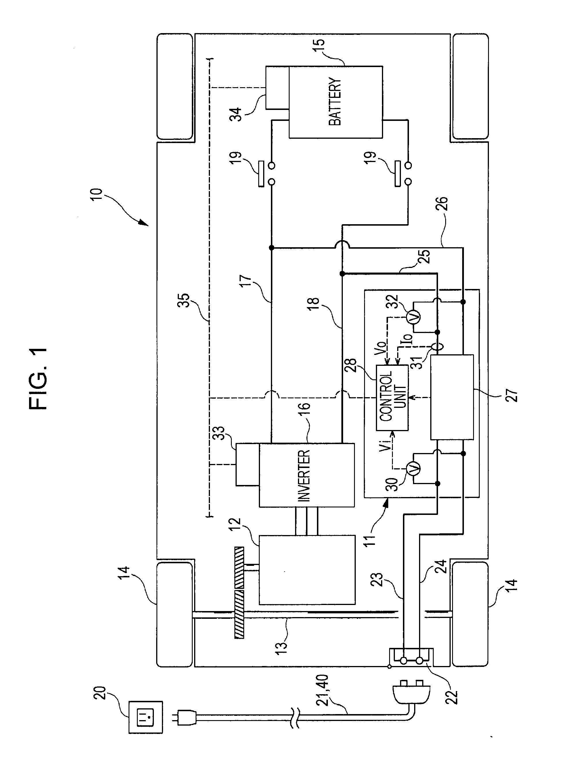
[0015]An embodiment of the present invention will hereunder be described with reference to the drawings. FIG. 1 is a schematic view showing a configuration of an electric vehicle 10. The electric vehicle 10 is equipped with a charging device 11 that is an embodiment of the present invention. As shown in FIG. 1, the electric vehicle 10 includes a motor-generator 12 which is connected to drive wheels by the intermediary of a drive axle 13. Furthermore, the electric vehicle 10 has a battery 15 as the electricity storage device which is connected to the motor-generator 12 by the intermediary of an inverter 16. Each of conducting lines 17 and 18 that connect the battery 15 and inverter 16 is provided with a main relay 19.

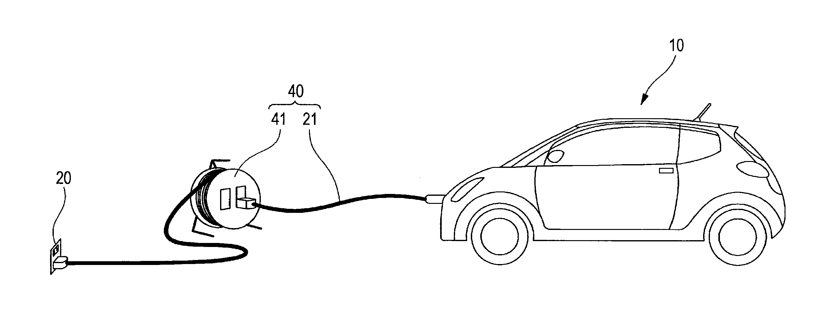
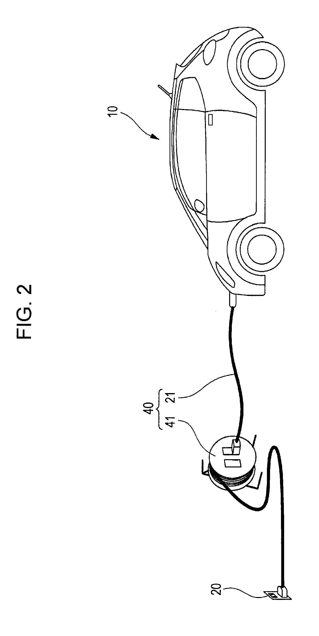
[0016]The electric vehicle 10 is provided with a charge socket 22 for connecting a charge cable 21 in order to charge the battery 15 with an external power source 20 (for example, AC 100 V). The charging device 11 mounted on the electric vehicle 10 converts supplied powe...


PUM


Abstract

When a battery of an electric vehicle charged with an external power source (AC 100 V), the electric vehicle and the external power source are connected with each other by the intermediary of a charging cable. Upon this charging, it is determined whether or not an input voltage from the external power source is 95 V or more. When the input voltage is less than 95 V, that is, a decline of the voltage in the charging cable is large, since a wiring resistance in the charging cable possibly increases, an upper limit of an output power to the battery is reduced. Consequently, the electric power delivered from the external power source can be limited, and thereby excessive heat generation is inhibited and safety is ensured. Furthermore, since the output power is caused to be limited when the wiring resistance possibly increases, the battery can be charged continuously.

Description

CROSS REFERENCES TO RELATED APPLICATIONS[0001]The present application claims priority from Japanese Patent Application No. 2010-069363 filed on Mar. 25, 2010, and is hereby incorporated by reference in its entirety.BACKGROUND OF THE INVENTION[0002]1. Field of the Invention The present invention relates to a charging device that is used by being connected to an external power source.[0003]2. Description of the Related Art[0004]In recent years, electric vehicles which are equipped with an electric motor for propulsion have been under development. The electric vehicle is equipped with an electricity storage device such as battery as well as a charging device, and can be charged with an external power source by connecting the electric vehicle with the external power source by the intermediary of a charging cable. Furthermore, in the field of hybrid electric vehicles that are equipped with an engine and electric motor for propulsion, so called a plug-in type vehicle the electricity stora...

Claims


Application Information

Patent Timeline
Patent Type & Authority Applications(United States)
IPC IPC(8): H02J7/04H02J7/00B60L3/00
CPCB60L11/1816B60L2230/12B60L2240/36Y02T90/14Y02T10/7005Y02T10/7088Y02T90/121H02J7/027B60L2240/529B60L2240/527Y04S30/14B60L53/14B60L53/65B60L58/21B60L53/18Y02T10/70Y02T10/7072Y02T90/12Y02T90/167H02J7/02H02J7/00309H02J7/0047Y02T90/16
Inventor OHTOMO, YOSUKESETA, ITARU
Owner SUBARU CORP
Why Eureka
Try Eureka