Power supply device capable of equalizing electrical properties of batteries

a power supply device and battery technology, applied in the direction of battery/fuel cell control arrangement, electrochemical generators, transportation and packaging, etc., can solve the problems of battery with completely the same properties not being manufactured, uneven voltage and remaining capacity, and particular batteries may be over-charged or over-charged, so as to reduce the amount of capacity to be discharged, the effect of keeping the balance among the batteries

Active Publication Date: 2011-09-29
SANYO ELECTRIC CO LTD
View PDF8 Cites 53 Cited by
  • Summary
  • Abstract
  • Description
  • Claims
  • Application Information

AI Technical Summary

Benefits of technology

[0010]To achieve the above object, a power supply device according to a first aspect of the present invention includes a series battery group 10 and cell block equalizing circuits 20. The series battery group 10 includes a plurality of rechargeable batteries 11 that are connected to each other in series. Each of the cell block equalizing circuits 20 discharges or charges batteries 11 composing the series battery group 10 so as to equalizes the electrical properties of the batteries 11. The series battery group 10 is divided into a plurality of cell blocks. The cell block equalizing circuits 20) serve as in-block equalization circuits each of which is connected to batteries 11) composing the corresponding cell block to equalize the electrical properties of the batteries 11) composing the corresponding cell block. The in-block equalization circuit includes a DC / DC converter, output control switches 22 and a switching control circuit 23. The DC / DC converter operates with being supplied with electric power from batteries 11 as power supply composing the corresponding cell block. Each of the output control switches 22 connects the output side of the DC / DC converter to the corresponding battery 11. The switching control circuit 23 controls ON / OFF of the output control switches 22. The DC / DC converter includes a transformer 21. The primary-side of the transformer 21 is connected through a primary-side switching element 41 to the series battery group 10 composed of the cell blocks. The transformer 21 includes charging secondary winding lines 24 and a discharging secondary winding line 26. The charging secondary winding lines can charge the batteries 11 composing the corresponding cell block. The discharging secondary winding line 26 can discharge the corresponding cell block. The charging secondary winding line 24 is connected to the corresponding battery 11 through a secondary-side rectification output circuit 25 and the corresponding output control switch 22. The discharging secondary winding line 26 is connected to a block discharging circuit through a block discharging switch 28. The block discharging switch 28 is controlled by the switching control circuit 23. The switching control circuit 23 controls the output control switches 22 of the corresponding cell block for equalizing the electrical properties of the batteries 11 composing the corresponding cell block. The switching control circuit 23 controls the block discharging switch 28 for equalizing the battery electrical properties of the cell blocks. According to this construction, it is possible to equalize not only the electrical properties of the batteries in the cell block but also the battery electrical properties of the cell blocks. Therefore, it is possible to keep the balance among the batteries of the entire power supply device. In particular, since a battery with small capacity is charged from other batteries, the amount of capacity to be discharged can be reduced, and additionally the rebalance can be acquired within a short time. In addition, since the amount of discharging current can be small, the amount of heat generation can be suppressed. Therefore, the circuitry of the power supply device can be small.

Problems solved by technology

However, practically, batteries with completely the same properties cannot be manufactured.
The unbalance among the batteries causes uneven voltages and remaining capacities after the batteries are repeatedly charged / discharged.
In addition, if the batteries have unbalanced battery voltages, a particular battery may be over-charged or over-discharged.
The over-charging / over-discharging operation may cause not only battery deterioration but also reduction in battery safety.
In addition, since a large number of, the rest of batteries to be discharged are reduced to the lowest voltage, the battery voltage unbalance tends to be large.
As a result, the capacity to be discharged from batteries with higher voltage will be large.
If the total discharged capacity is large, or if the discharged capacity of a particular battery is large, the amount of discharging heat generation will be large.
In particular, if the amount of heat generation of a number of discharging resistors is large, it is difficult to effectively dissipate heat generated by the discharging resistors mounted on a circuit board.
In addition, since high power consumption discharging resistors have a large exterior shape, actually, it is difficult to mount a number of such discharging resistors on the circuit board.
For this reason, actually, it is difficult to mount the large power consumption discharging resistors on the circuit board.
The reason is that the discharging current relates to the power consumption of the discharging resistor.
For this reason, it is difficult for a small discharging resistor to be mounted on the circuit board to quickly reduce the voltage of the battery.
Accordingly, in this case, there is a disadvantage that it takes time to equalize the voltages of the batteries.

Method used


Image

  • Power supply device capable of equalizing electrical properties of batteries
  • Power supply device capable of equalizing electrical properties of batteries
  • Power supply device capable of equalizing electrical properties of batteries

Examples


first embodiment

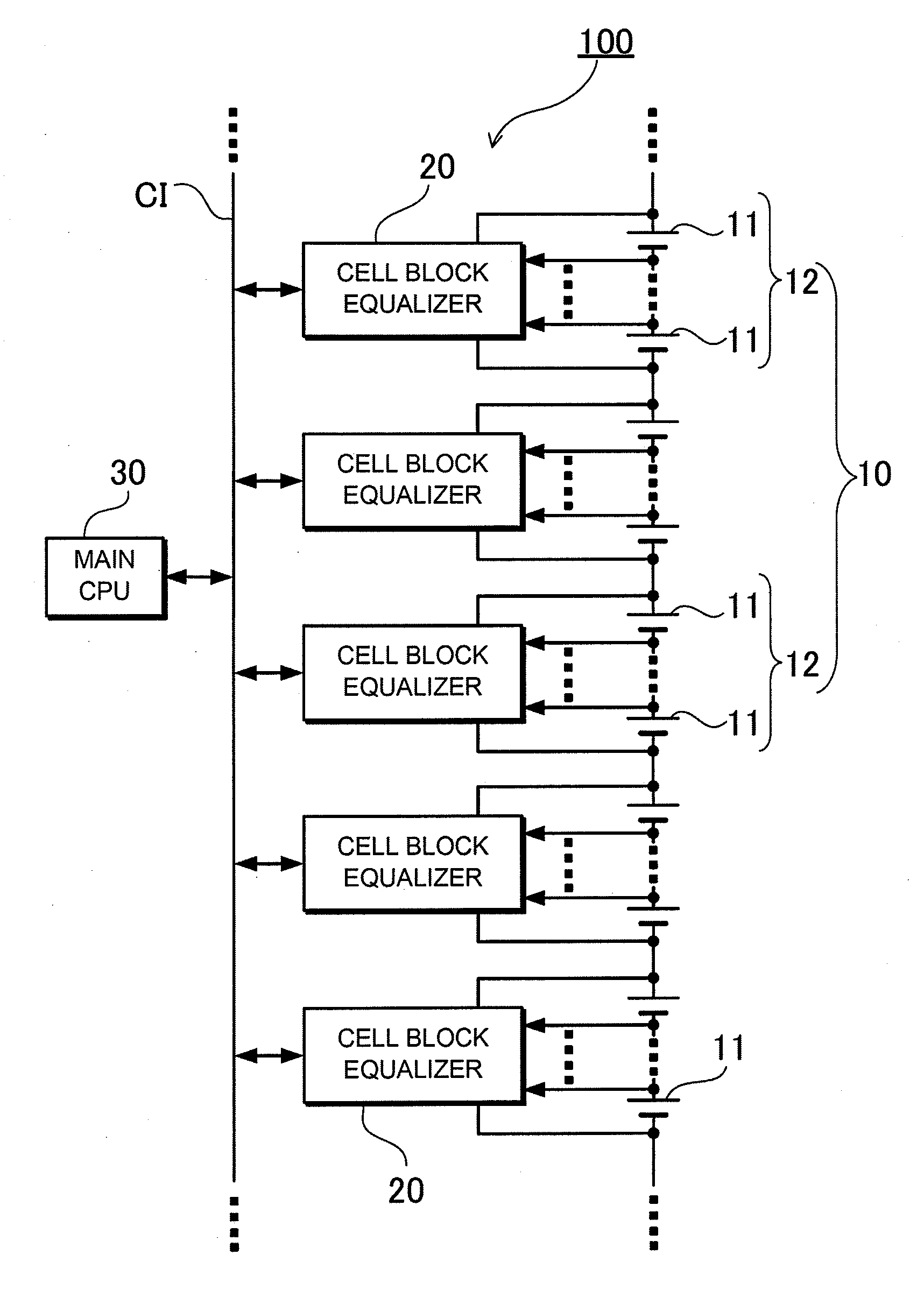
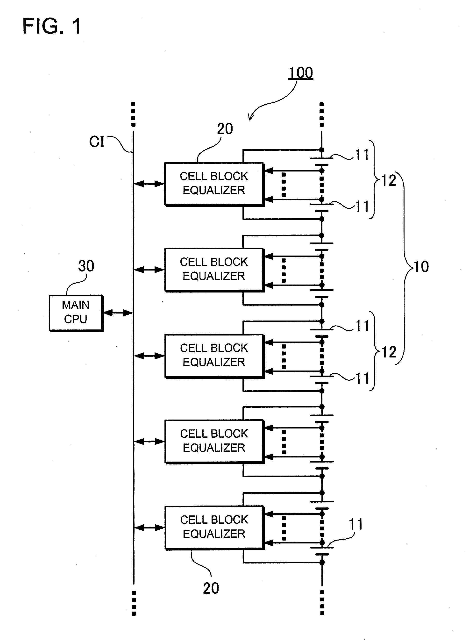
[0029]FIG. 1 is a block diagram showing the construction of a power supply device 100 according to a first embodiment of the present invention. As shown in this block diagram, the power supply device 100 includes a series battery group 10 that includes a number of batteries 11 that are serially connected to each other. The series battery group 10 is divided into a plurality of blocks. Each of the blocks composes a cell block 12 that includes a predetermined number of batteries 11 that are serially connected to each other. Each of the cell blocks 12 is connected to corresponding one of cell block equalizing circuits 20 that suppresses the property variation among the batteries that are included in the cell block 12. A main CPU 30 controls the cell block equalizing circuits 20 for equalization where the property variation among the cell blocks is suppressed. The main CPU 30 is connected to and can communicate with the cell block equalizing circuits 20 through a communication interface...

second embodiment

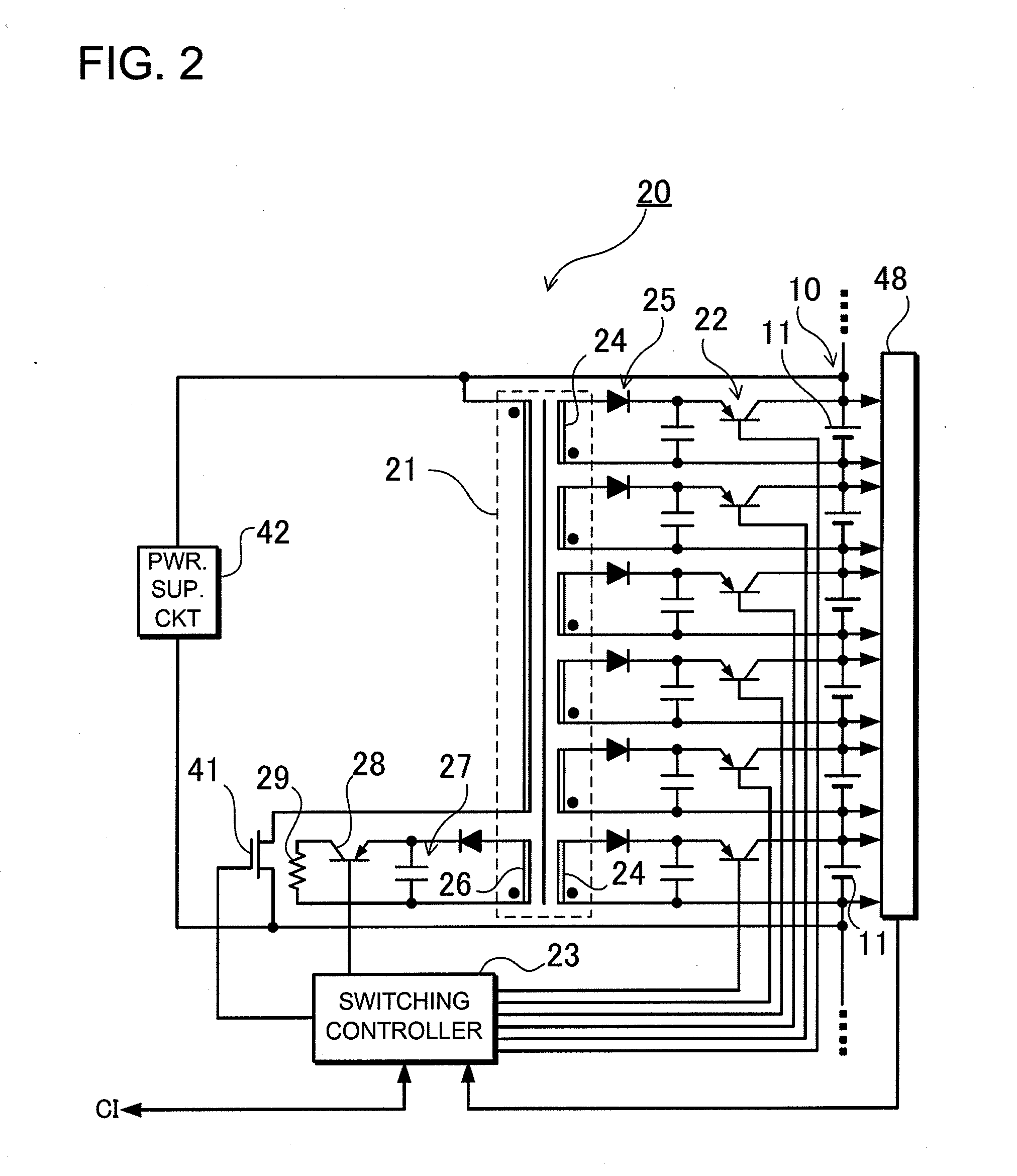
[0051]The embodiment shown in FIG. 2 has been described in that the power supply circuit 42 reduces the block voltage, which is the total voltage of the series battery group 10, by using the DC / DC converter or the like, and supplies electric power for driving members such as the switching control circuits 23. However, in this construction, if the difference is large between the block voltage and electric power for driving a microcomputer that composes the member, the voltage conversion loss will be large. For this reason, it is preferable that voltage be provided from the discharging secondary winding line 26 as discussed above so that the voltage is used as the power supply voltage for driving the microcomputer. The reason is that electric power to be consumed in discharging equalization can be effectively used. FIG. 5 shows an exemplary diagram of this type of circuit according to a second embodiment. A cell block equalizing circuit 20B of this illustrated power supply device has ...

third embodiment

Additional Battery Charging Function

[0054]The electric power produced in the equalization can be used to charge the additional battery. FIGS. 6 and 7 show exemplary diagrams of this type of circuit according to a third embodiment. FIG. 6 is a block diagram of a power supply device 300 with an additional battery 50 connected to the power supply device 300. FIG. 7 shows an exemplary circuit of cell block equalizing circuit 20C shown in FIG. 6. In the case of vehicle use, for example, the illustrated additional battery 50 can be a 12-V lead battery for vehicle electrical components, while the series battery group 10 can be a battery for driving the vehicle. In the power supply device 300 shown in the block diagram of FIG. 6, in addition to the communication interface CI, which connects the cell block equalizing circuits to the main CPU 30 as shown in FIG. 1, an additional battery connecting interface BI is provided for charging the additional battery 50. Thus, the cell block equalizing...


PUM


Abstract

A transformer 21 includes charging secondary winding lines 24 that can charge batteries 11 composing a corresponding cell block, and a discharging secondary winding line 26 that can discharge the corresponding cell block. Each of the charging secondary winding lines 24 is connected to corresponding one of the batteries 11 through corresponding one of secondary-side rectification output circuits 25 and corresponding one of output control switches 22. The discharging secondary winding line 26 is connected to a block discharging circuit through a block discharging switch 28. A switching control circuit 23 controls the block discharging switch 28. The switching control circuit 23 controls the output control switches 22 so that the electrical properties of the batteries 11 in the cell block are equalized. In addition, the switching control circuits 23 control the block discharging switches 28 so that the electrical properties of the batteries among the cell blocks are equalized.

Description

BACKGROUND OF THE INVENTION[0001]1. Field of the Invention[0002]The present invention relates to a power supply device that includes a number of batteries serially connected to each other for supplying high output voltage, and in particular to a power supply device for suitably driving vehicles.[0003]2. Description of the Related Art[0004]Vehicle power supply devices include a plurality of batteries that are serially connected to each other to increase the output voltage of the power supply devices. In such power supply devices, the serially-connected batteries are charged at the same amount of charging current, and are discharged at the same amount of current. For this reason, if all the batteries have the completely same properties, their battery voltages and remaining capacities will not be unbalanced. However, practically, batteries with completely the same properties cannot be manufactured. The unbalance among the batteries causes uneven voltages and remaining capacities after ...

Claims


Application Information

Patent Timeline
Patent Type & Authority Applications(United States)
IPC IPC(8): H02J7/00H02J7/02
CPCY02T10/7055H02J7/0018Y02E60/10Y02T10/70B60L58/22H01M10/441H02J7/0019
Inventor FURUKAWA, KIMIHIKO
Owner SANYO ELECTRIC CO LTD
Why Eureka
Try Eureka