Magnetic flux leakage inspection device

Inactive Publication Date: 2011-09-29
OLYMPUS NDT
View PDF2 Cites 30 Cited by
  • Summary
  • Abstract
  • Description
  • Claims
  • Application Information

AI Technical Summary

Benefits of technology

[0018]It is further an object of the present disclosure to employ an adjustable magnetic yoke to conveniently adjust the strength of the magnetic field during operations.
[0019]It is further an object of the present disclosure to make use of a combination of fixed and displaceable permanent magnets to provide a magnetic yoke which allows the magnetic field to be continuously adjusted.
[0020]In one embodiment of the current invention, a row of four permanent magnets are used to provide a combined magnetic field in a yoke wherein rotation of two of the magnets allows the strength of the magnetic field to be easily adjusted in a continuous fashion.
[0021]In another embodiment of the current invention, two rows of four permane

Problems solved by technology

Localized defects from corrosion, pitting and the like produce irregularities in the highly regular form of the flux pattern that “leaks out” of the test object.
There is a practical limitation, however, to the magnitude of the largest magnetizing force that can be applied.
That is the attractive magnetic force between the magnets in the device and the material being magnetized can become unmanageably large.
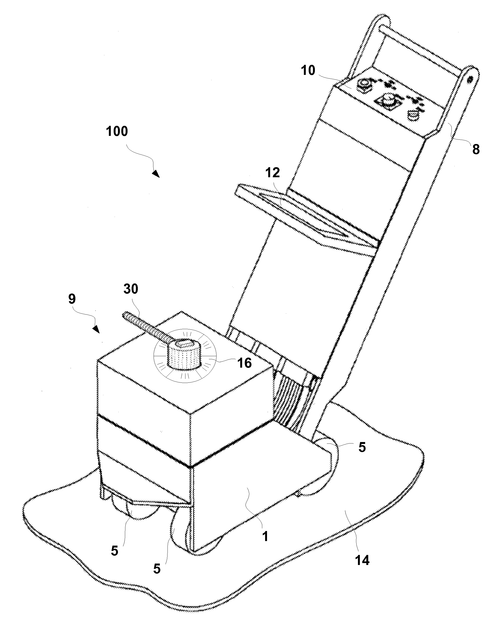
Currently available magnetic inspection devices are generally difficult to operate.
The needed strength of the magnetic inspection power creates attraction between the on-board magnet(s) and the steel plate (test object), such as an oil tank bottom, making it very difficult to freely move the device over the inspection surface.
Even with the on-board driving motor for the wheels, manipulating the device in the course of inspecting a full tank bottom can be a laborious operation.
Maneuvering the device is laborious in part because the operator must first “break” the attractive magnetic force whenever it is desired to re-position the device for inspecting a new region of the test object, for example when a sidewall is reached, or to navigate the device around or over obstacles such as plate welds.
Operators commonly find it burdensome to manipulate the device back and forth over the tank bottom when the total attractive force exceeds about 200 pounds (about 90 kilograms) and extremely difficult if not prohibitively exhausting when the attractive force exceeds about 700 pounds (about 300 kilograms).
The existing magnetic yokes used for these devices are afflicted by the same inconveniences as the magnetic flux leakage inspection devices mentioned above, notably poor maneuverability, d

Method used


Image

  • Magnetic flux leakage inspection device
  • Magnetic flux leakage inspection device
  • Magnetic flux leakage inspection device

Examples


Embodiment Construction

[0031]Referring to FIG. 1, one embodiment (embodiment A) of a magnetic flux leakage inspection device 100 according to the present invention is shown. The device includes an inspection carriage assembly 9 mounted on wheels 5 and a handle portion 8 by which an operator steers and manipulates the device. Preferrably mouted on handle portion 8 are a control panel 10 for controlling the operation of the device and an interface screen 12 for displaying inspection results and serving as an interface for the operator communicating with the device. The device is shown positioned on a portion of a test object 14, which is under inspection. Test object 14 is composed of a magnetizable material and for the case of storage tank bottoms, it is generally a ferromagnetic steel plate.

[0032]A novel aspect of device 100 representing a significant improvement to the existing magnetic flux leakage inspection devices is that device 100 comprises a scan bar assembly 1 containing a plurality of magnets, t...


PUM


Abstract

Disclosed are a method and an improvement to the existing conventional magnetic flux leakage inspection device that employ some fixed magnets that are fixed inside the magnet yoke and some movably adjustable magnets, allowing their dipole orientation to be adjusted between 0° and 180° relative to that of the fixed magnets. A lever and gear set connected to the adjustable magnets can be operated to achieve desired level of magnetic strength of the device, including turning off the whole magnetic field, by causing the fields of the fixed and adjustable magnets to cancel each other. The disclosed adjustable yoke can also be used in other NDT/NDI applications where providing an adjustable magnetic strength is desirable.

Description

FIELD OF THE INVENTION[0001]This invention relates to non-destructive testing and inspection (NDT / NDI) devices that employ magnetic fields induced by permanent magnets during the inspection, more particularly to an improved magnetic yoke which facilitates adjustment of the strength of the magnetic field in the devices.BACKGROUND OF THE INVENTION[0002]It is known in the art, such as in U.S. Pat. No. 4,814,705 that discontinuities such as cracks or pits below the surface of a test object of magnetizable material can be detected by magnetizing the material and sensing variations in leakage field near the surface of the test object. The device disclosed in U.S. Pat. No. 4,814,705 utilizes one or more magnets and an array of magnetic flux leakage sensors which are moved over the surface of the test object in close proximity. When a local region of the test object under the magnet is free of defects, it produces an induced magnetic flux of a known form that is highly regular. Localized de...

Claims


Application Information

Patent Timeline
IPC IPC(8): G01N27/82
CPCG01N27/82H01F7/0294H01F7/0226
Inventor LEPAGE, BENOITLIU, CHUNYAN TRICIA
Owner OLYMPUS NDT
Why Eureka
Try Eureka