Time resolved photoluminescence imaging systems and methods for photovoltaic cell inspection

a photoluminescence imaging and photovoltaic cell technology, applied in the field of time resolved photoluminescence imaging systems and methods for photovoltaic cell inspection, can solve the problems of inability to achieve in-line measurements, image does not have a high resolution, and exposure of at least a few seconds,

Inactive Publication Date: 2011-09-29
INTEVAC
View PDF9 Cites 51 Cited by
  • Summary
  • Abstract
  • Description
  • Claims
  • Application Information

AI Technical Summary

Benefits of technology

[0009]The following summary of the invention is included in order to provide a basic understanding of some aspects and features of the invention. This summary is not an extensive overview of the invention and as such it is not intended to particul...

Problems solved by technology

If the light intensity is too high, the image does not have a high resolution because the high intensity light tends to blur the details.
This however, requires an exposure of at least a few seconds and more typically a minute or more to collect the image.
This technique however is not suited to in-line measurements and becomes a bottleneck in the process.
InGaAs focal plane arrays can also co...

Method used


Image

  • Time resolved photoluminescence imaging systems and methods for photovoltaic cell inspection
  • Time resolved photoluminescence imaging systems and methods for photovoltaic cell inspection
  • Time resolved photoluminescence imaging systems and methods for photovoltaic cell inspection

Examples


Embodiment Construction

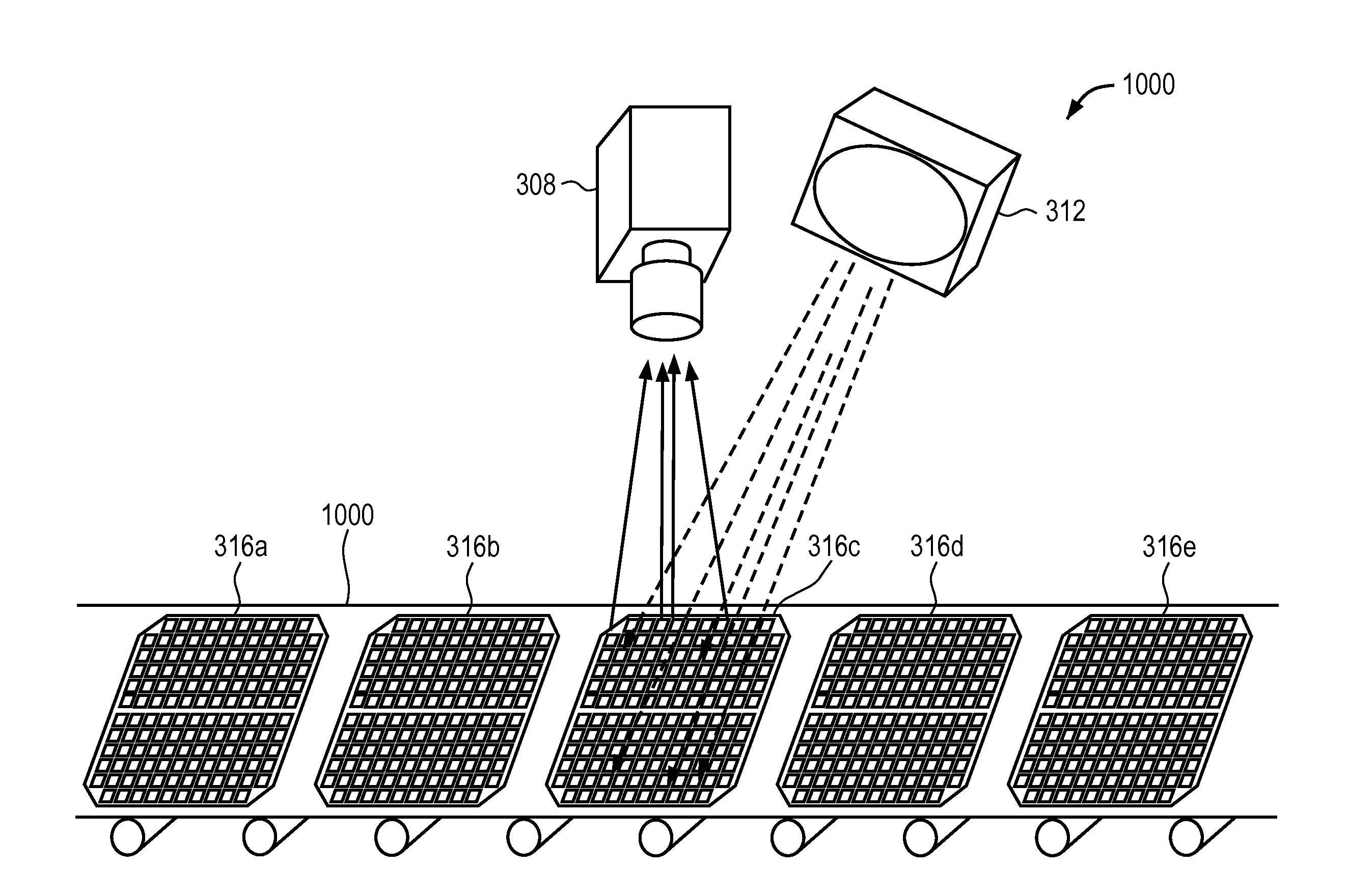
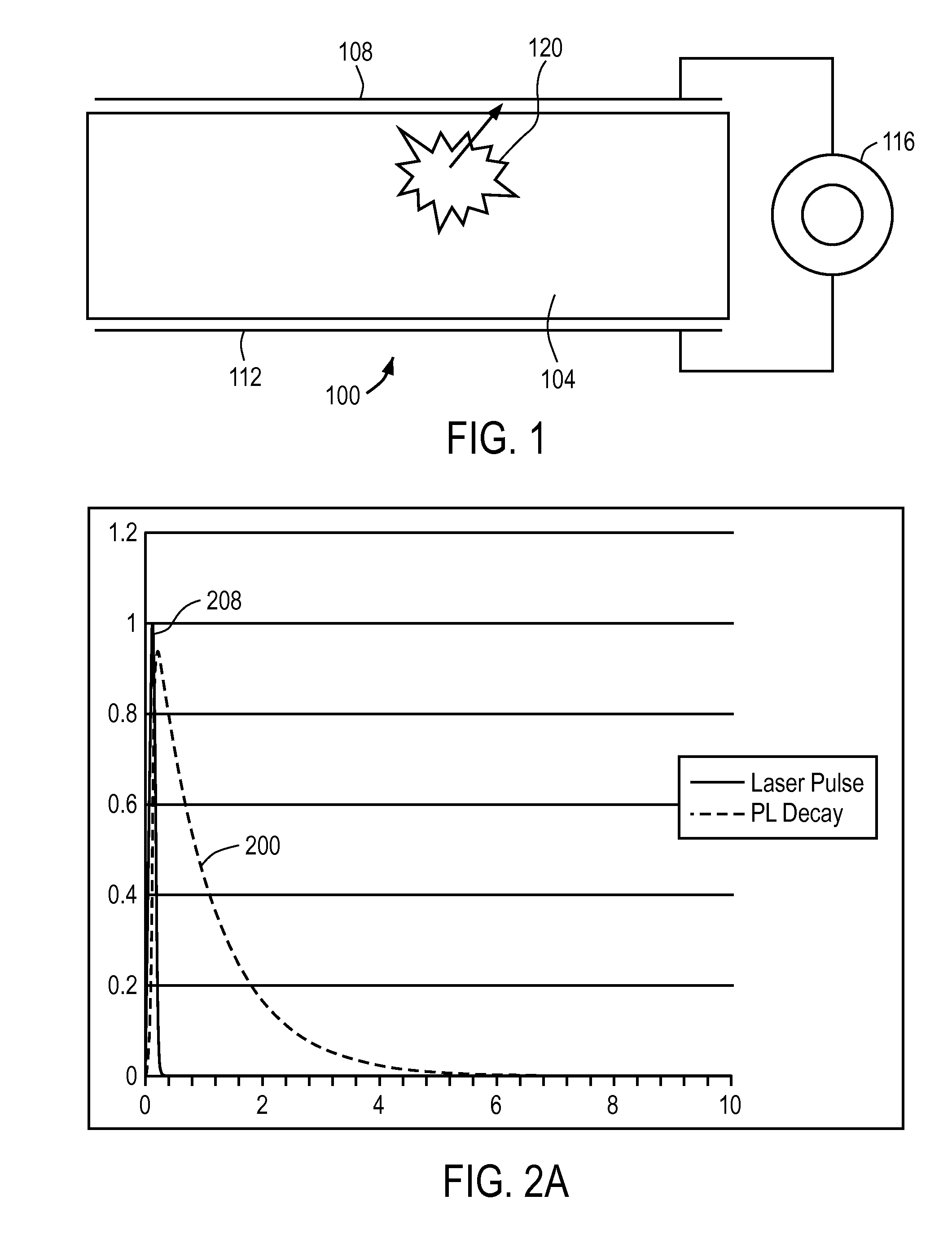
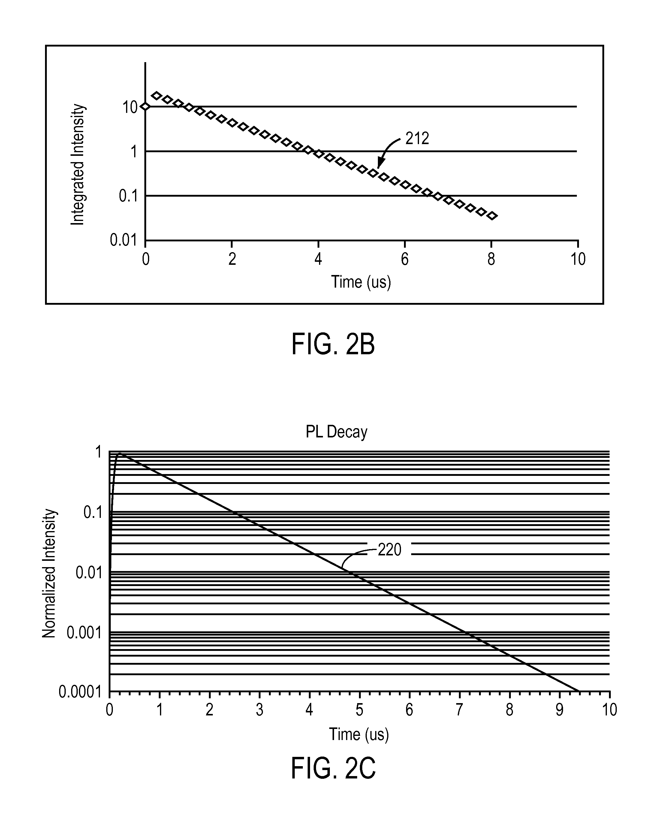
[0040]A time-resolved photoluminescence technique is disclosed for imaging and inspecting photovoltaic cells. Photoluminescence intensity is directly proportional to carrier lifetime: −IPL=c Δn=cT, where n is the carrier charge density, c is a constant and T is the lifetime. A pulsed light source flashes the wafer, generating excess carriers in the silicon, causing photoluminescence. The rate of carrier recombination is monitored by imaging the photoluminescence decay over time using a photodetector that has a fast response. A photoluminescence decay curve is generated, and the effective lifetime is extracted from the curve. As a result, the effective lifetime is measured directly.

[0041]An embodiment of the invention will now be described in detail with reference to FIG. 1. FIG. 1 illustrates an exemplary photovoltaic cell 100. The photovoltaic cell typically includes a semiconductor wafer 104 that converts energy from sunlight into electrical energy. The semiconductor wafer 104 is ...


PUM


Abstract

A time-resolved photoluminescence technique is disclosed to image photovoltaic cells and wafers. The effective lifetime is measured directly using a photodetector that has a fast response. A pulsed light source flashes the wafer, generating excess carriers in the silicon. The rate of carrier recombination is monitored by imaging the photoluminescence decay over time. An effective lifetime can be extracted from the photoluminescence decay curve, which can be used to determine the quality of the photovoltaic cells and wafers.

Description

CROSS-REFERENCE TO RELATED PATENT APPLICATION[0001]This application claims the benefit of the Provisional Application No. 61 / 318,738, filed on Mar. 29, 2010, the disclosure of which is hereby incorporated herein in its entirety by reference.BACKGROUND[0002]1. Field[0003]The subject invention relates to time resolved photoluminescence imaging systems and methods for photovoltaic cell inspection.[0004]2. Related Art[0005]Photoluminescence is the re-emission of light after absorbing light of a higher energy (shorter wavelength). Visible light from a solar lamp, laser, or LED excites electrons in photovoltaic wafer materials such as silicon. Most of the photo-generated electrons give up their energy as heat, but a small fraction of the electrons recombine with holes in the silicon, emitting a photon (radiative recombination). More defects in the silicon result in more energy lost as heat and fewer emitted photons, while fewer defects in the silicon result in more radiative recombination...

Claims


Application Information

Patent Timeline
IPC IPC(8): H04N7/18
CPCH04N7/183G01N21/6489G01N21/6408G01N21/9501G01N2021/646
Inventor TRUE, BRUCE
Owner INTEVAC
Why Eureka
Try Eureka