Clamping device for cylinder sleeves and use thereof, and mud pump having a clamping

a technology of mud pump and cylinder sleeves, which is applied in the direction of sleeve/socket joint, engine without rotary main shaft, coupling, etc., can solve the problems of corrosive drilling mud, increased wear of cylinder sleeves, and general corrosion of drilling mud, etc., to achieve uniform and defined contact force, easy to use, and inexpensive

Active Publication Date: 2011-09-29
BENTEC DRILLING & OILFIELD SYST
View PDF12 Cites 22 Cited by
  • Summary
  • Abstract
  • Description
  • Claims
  • Application Information

AI Technical Summary

Benefits of technology

[0028]An object of the invention, therefore, is to provide a fastening device which avoids the disadvantages of the prior art and at the same time is inexpensive and easy to use, and which ensures a uniform and defined contact force on the sealing face of the cylinder sleeve, and therefore ensures its function. A further object of the invention is a piston pump or plunger pump that is suited for this purpose, and a method for installation.

Problems solved by technology

On the one hand, these cylinder sleeves are subjected to greater wear due to the pumping medium, i.e., the drilling mud, which is extremely corrosive and in particular is abrasive due to solids.
Leaks in this region are hazardous as well as costly.
In addition, the drilling mud that is used is generally corrosive.
The wing clamps have the major disadvantage that they are very unwieldy, and the torque may be applied to the cylinder sleeve only in a very imprecise manner using a torque wrench.
In addition, this factor varies greatly as a result of the conical surface, which may become worn or soiled (oily), which has a direct influence on the contact force that is being transmitted.
Installing the clamp requires a great expenditure of force and also entails a certain risk of injury.
Monitoring of the contact force is not possible without retightening.
In this system the supporting bolts are elongated using a hydraulic pump, or the hydraulic force acts against a separate spring assembly, thus causing a deflection.
However, it is disadvantageous that the cylinder sleeve and the clamping element must be lifted in two crane hoisting operations, and therefore separately.
The hydraulic components and in particular the filler are susceptible to damage, or are subject to failure and the need for frequent repairs.
Due to the more complex design, the system is approximately twice as expensive as the wing clamp having a liner receptacle.
Here as well, subsequent monitoring of the contact force is not possible, although there is a risk of the cylinder sleeve or liner detaching or loosening as the result of vibration from the drilling operation or the drilling mud injection process.
However, the only possibility for applying torque, which, however, is very imprecise, is for the nut to be continuously struck with a hammer with the full strength of the installer.
The thread is also susceptible to corrosion and damage, which together with the accompanying wear results in even greater variation of the contact force.
In addition, the strength of the installer is a factor that is not easily calculated.
The disadvantage of DE 3831909 A1 is the guiding of the piston rod in the cylinder, resulting in a statically indeterminate bearing of the piston rod, which causes increased wear on multiple wearing parts.
This guiding also requires time-consuming replacement of the piston.
Rapid installation and deinstallation of the piston and the cylinder sleeve is therefore not possible.
In addition, the supplying of pressure media is complicated, and cannot be used in a pump having an integrated pressure media supply system.
Another disadvantage is the action on the described pipe / flange connection, which is directed orthogonally with respect to the longitudinal axis of the plug-in socket.
The adjustable stress-measuring bolt disclosed in U.S. Pat. No. 4,981,401 has a complicated mechanism which allows incorrect operation, and which due to the prevailing harsh conditions is not suitable for applications for conveying drilling fluid in the drilling of boreholes.
The cited document does not disclose a particular fastening of the cylinder of the fluid processing machine which is suitable for ensuring short setup times and a low expenditure of effort, especially in a harsh environment.

Method used


Image

  • Clamping device for cylinder sleeves and use thereof, and mud pump having a clamping
  • Clamping device for cylinder sleeves and use thereof, and mud pump having a clamping
  • Clamping device for cylinder sleeves and use thereof, and mud pump having a clamping

Examples


Embodiment Construction

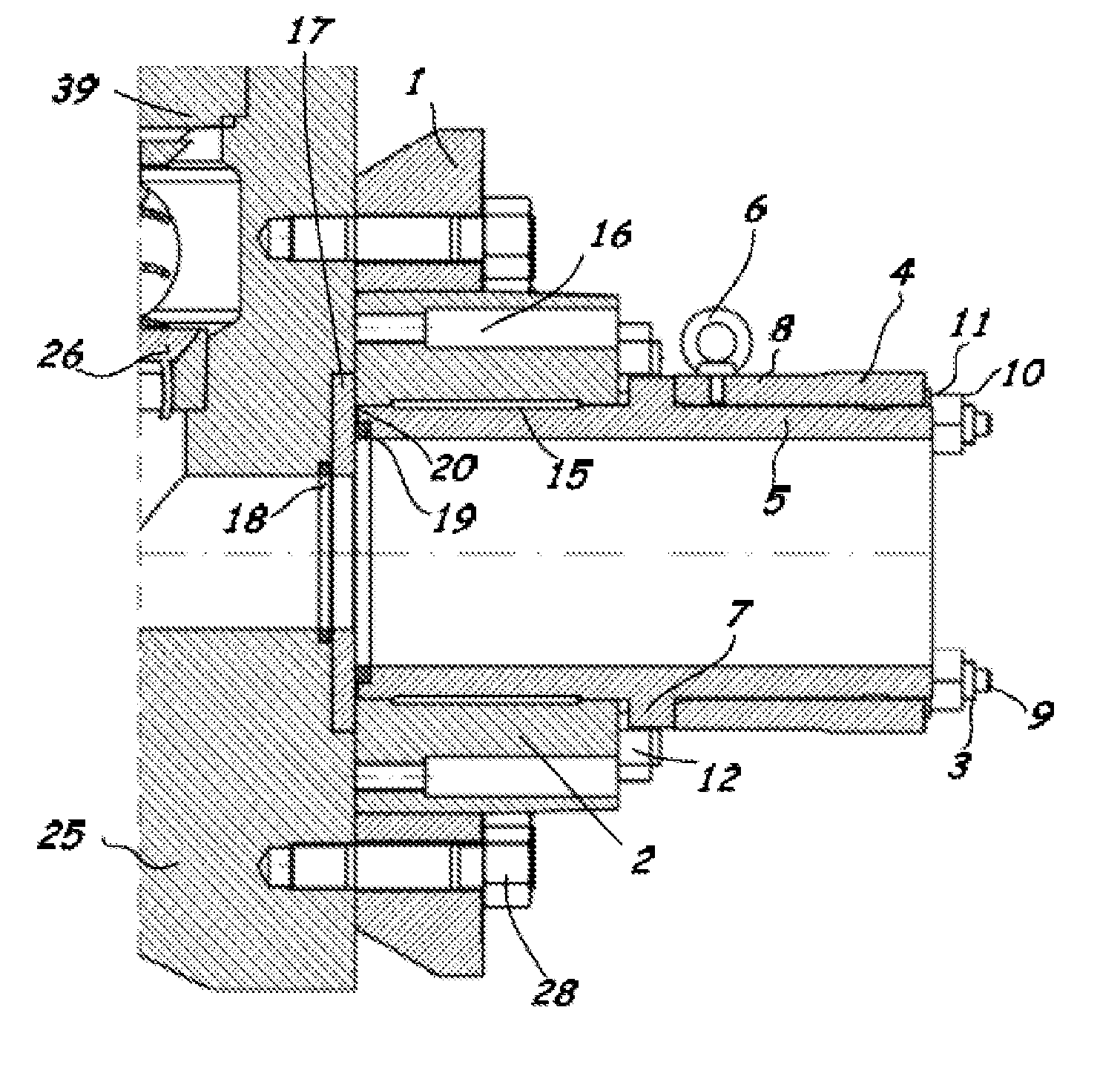
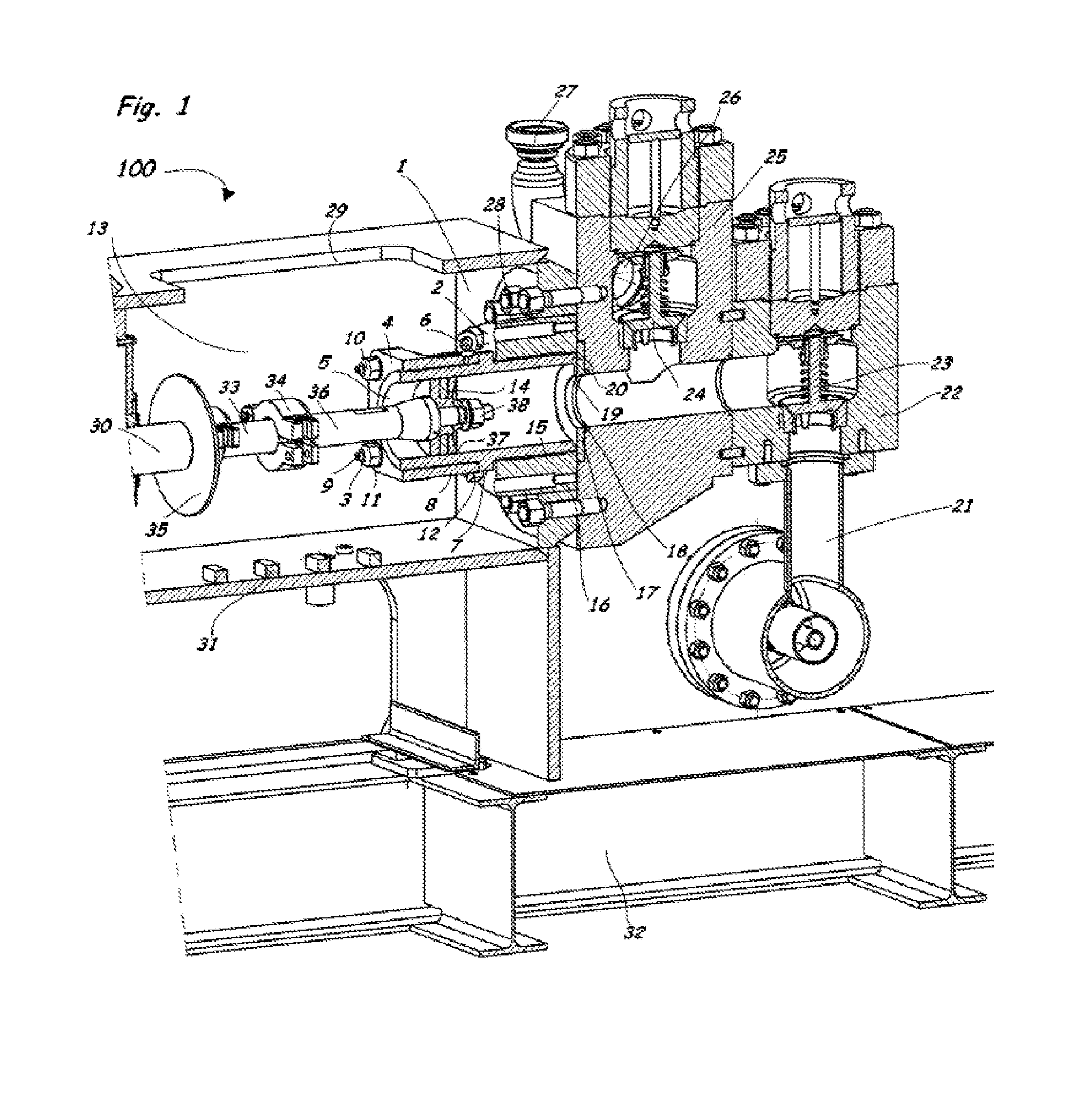
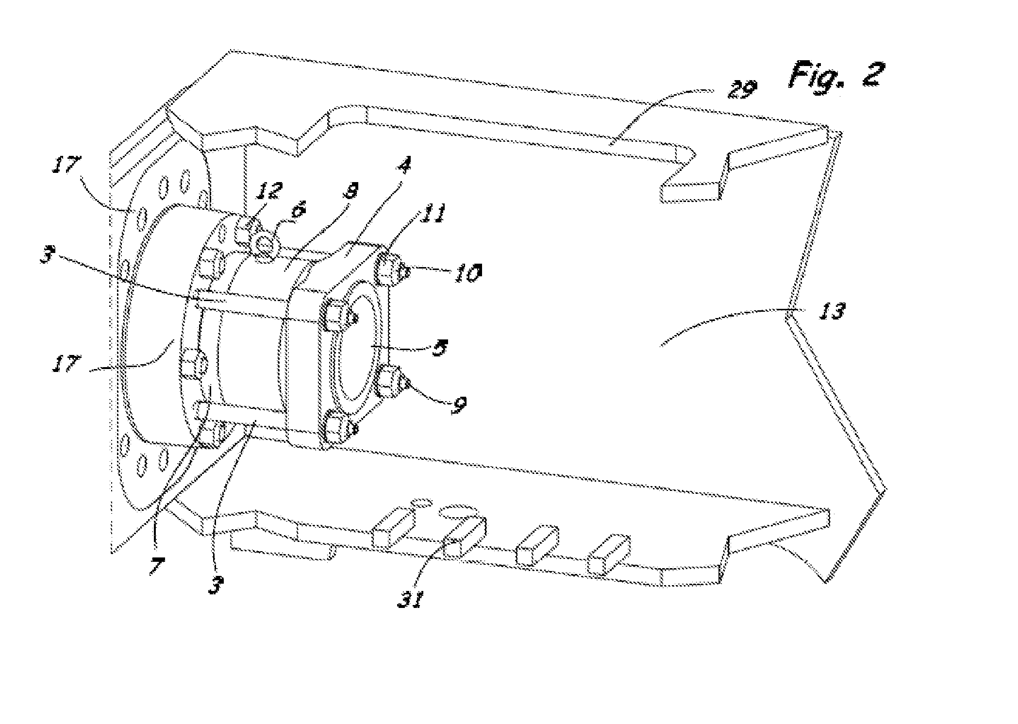
[0048]FIG. 1 shows a clamping device for a cylinder sleeve 5 as part of a mud pump. The cross section of the front portion of a mud pump is illustrated, a mud pump having the clamping device 5 according to the invention being represented by reference numeral 100. Depending on the configuration, a mud pump may have multiple cylinder sleeves together with the corresponding piston or plunger.

[0049]The piston rod 36 projects from the left into the pump housing 13, which is shown in a cutaway view in a partial illustration. The piston rod is composed of a crosshead piston rod 30 on which is mounted a baffle plate 35 which protects the portion of the pump behind the baffle plate from drilling mud discharge in the event of seal failure. A connecting element 33 is fastened to the crosshead piston rod 30 via a wing clamp. The actual piston rod 36 is connected to the connecting element 33 via a further wing clamp 34. The actual piston 14 is fastened at its front end via the piston nut 38. The...


PUM

PropertyMeasurementUnit
pressureaaaaaaaaaa
inner diameteraaaaaaaaaa

Abstract

Clamping device for cylinder sleeves of a pump system, and a piston pump or plunger pump for conveying drilling fluid during drilling of boreholes, particularly in the field of oil and natural gas production, and its use. Pump system includes a pump unit and a driving rotary drive unit. Clamping device for cylinder sleeve of a piston pump or plunger pump includes a cylinder sleeve receptacle, a clamping element provided at the pump, and cylinder sleeve or a portion of the cylinder sleeve provided between the clamping element and the cylinder sleeve receptacle, Clamping element and cylinder sleeve receptacle are connected by a connecting apparatus.

Description

CROSS-REFERENCE TO RELATED APPLICATIONS[0001]This application is a continuation of application no. PCT / DE2009 / 001705, filed Dec. 3, 2009, which claims the priority of German application no. 10 2008 060 659.6, filed Dec. 8, 2008, and each of which is incorporated herein by reference.FIELD OF THE INVENTION[0002]The invention relates to a clamping device for cylinder sleeves of a pump system, and a piston pump or plunger pump for conveying drilling fluid during drilling of boreholes, in particular in the field of oil and natural gas production. This pump system consists of a pump unit and a driving rotary drive unit. The invention further relates to the use of a clamping device in a piston pump or plunger pump.BACKGROUND OF THE INVENTION[0003]In the drilling of boreholes, the injection of mud, and drilling mud, respectively, into the drill string or the borehole via the pump system serves several purposes. The drilling mud is used to remove the extracted drill cuttings and spoils, and ...

Claims


Application Information

Patent Timeline
Patent Type & Authority Applications(United States)
IPC IPC(8): F04B53/16B23P11/00F16L21/08
CPCF04B47/00Y10T29/49236F04B53/164
Inventor CORDES, MALTEGELKER, MICHAEL
Owner BENTEC DRILLING & OILFIELD SYST
Why Eureka
Try Eureka