Current collector for non-aqueous electrolyte secondary battery, electrode, non-aqueous electrolyte secondary battery, and method for producing the same

a technology of non-aqueous electrolyte secondary batteries and current collectors, which is applied in the direction of cell components, final product manufacturing, sustainable manufacturing/processing, etc., can solve the problems of difficult utilization of ptl 1 technique, difficult work of thin metal foils, and gradual change of thickness, so as to reduce the difference in current density between the distant and the close region, prevent the promotion of deterioration of active materials, and reduce the amount of heat.

Inactive Publication Date: 2011-09-29
PANASONIC CORP
View PDF3 Cites 10 Cited by
  • Summary
  • Abstract
  • Description
  • Claims
  • Application Information

AI Technical Summary

Benefits of technology

[0017]According to the invention, the open area ratio of the distant region of the metal foil is larger than that of the close region. Thus, the electrical resistance of the close region is smaller than that of the distant region. As a result, the difference in current density between the distant region and the close region is decreased. It is thus possible to decrease the difference in the amount of heat produced between the distant region and the close region and make the amounts of heat produced in the respective parts of the current collector due to passage of current uniform.
[0018]This can prevent promotion of deterioration of the active material in a specific part of the current collector, in particular, in a region close to the portion to be connected to the external terminal and prevent promotion of decomposition of the electrolyte. Therefore, the cycle characteristics of the non-aqueous electrolyte secondary battery can be improved.

Problems solved by technology

Such a very thin metal foil is very difficult to work so that its thickness changes gradually.
Therefore, the technique of PTL 1 is actually very difficult to utilize, although it may be theoretically correct.

Method used


Image

  • Current collector for non-aqueous electrolyte secondary battery, electrode, non-aqueous electrolyte secondary battery, and method for producing the same
  • Current collector for non-aqueous electrolyte secondary battery, electrode, non-aqueous electrolyte secondary battery, and method for producing the same
  • Current collector for non-aqueous electrolyte secondary battery, electrode, non-aqueous electrolyte secondary battery, and method for producing the same

Examples


embodiment 1

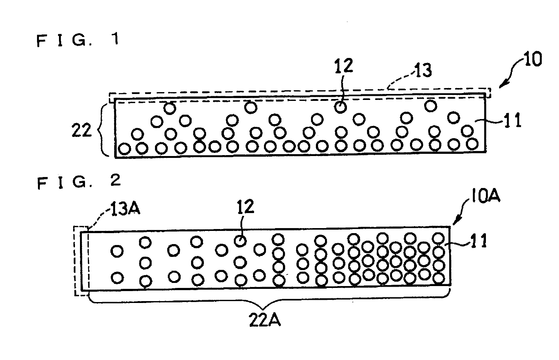
[0037]FIG. 1 is a schematic plan view of the structure of a current collector for a non-aqueous electrolyte secondary battery according to Embodiment 1 of the invention.

[0038]A current collector 10 illustrated therein comprises a metal foil 11 having a rectangular shape. The metal foil 11 has a plurality of through-holes 12 in a predetermined arrangement.

[0039]The current collector 10 has one end 13 in the width direction, to which an electrode lead (not shown) is attached. That is, the one end (long-side end) 13 of the current collector 10 in the width direction is a portion to be connected to an external terminal where the current is concentrated. The other portion of the current collector 10 is a current collection region 22 where an active material is supported. As used herein, a rectangular shape refers to a shape having a pair of long-side ends and a pair of short-side ends.

[0040]With respect to the arrangement of the through-holes 12, it is preferable to form the through-hole...

embodiment 2

[0053]Next, Embodiment 2 of the invention is described.

[0054]FIG. 2 is a schematic plan view of the structure of a current collector for a non-aqueous electrolyte secondary battery according to Embodiment 2. In FIG. 2, the same components as those of FIG. 1 are given the same reference characters.

[0055]A current collector 10A illustrated therein also comprises a rectangular metal foil 11 and the metal foil 11 has a plurality of through-holes 12, in the same manner as the current collector 10 of FIG. 1. The current collector 10A is different from the current collector 10 of FIG. 1 in that an electrode lead (not shown) is attached to one end (short-side end) 13A in the longitudinal direction. That is, the one end 13A of the current collector 10A in the longitudinal direction is the portion to be connected to an external terminal. The other portion of the current collector 10A is a current collection region 22A where an active material is supported.

[0056]In the current collector 10A, t...

embodiment 3

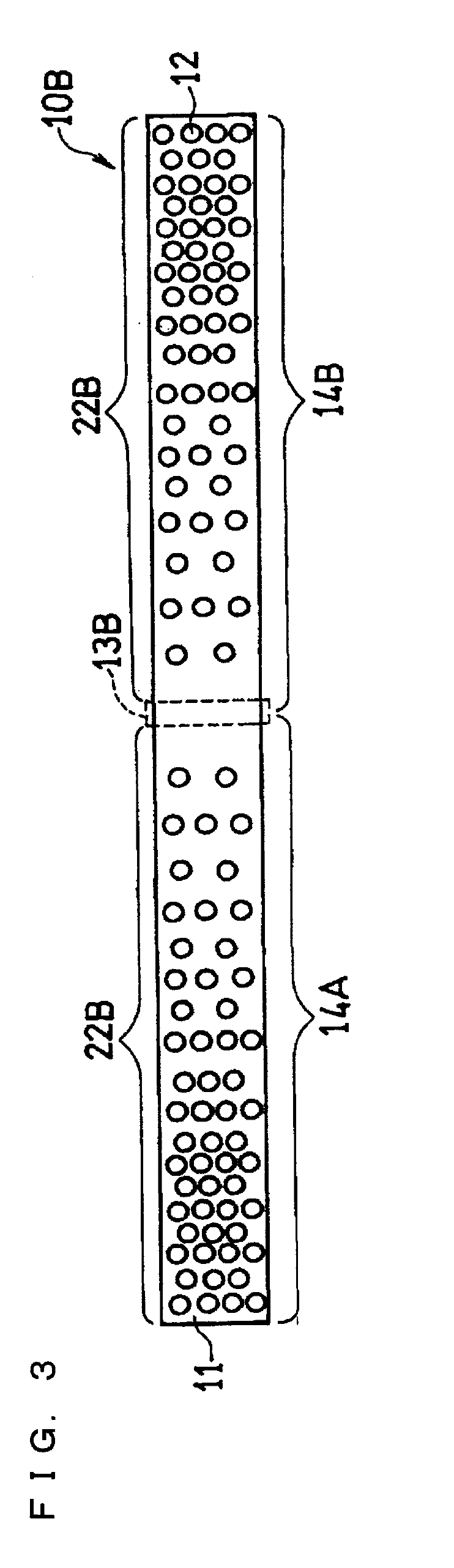
[0058]Next, Embodiment 3 of the invention is described. FIG. 3 is a schematic plan view of the structure of a current collector for a non-aqueous electrolyte secondary battery according to Embodiment 3. In FIG. 3, the same components as those of FIG. 1 are given the same reference characters.

[0059]A current collector 10B illustrated therein also comprises a metal foil 11 and the metal foil 11 has a plurality of through-holes 12, in the same manner as the current collector 10 of FIG. 1. The current collector 10B is different from the current collector 10 of FIG. 1 in that an electrode lead (not shown) is attached to a middle portion 13A in the longitudinal direction. That is, the middle portion 13B of the current collector 10B in the longitudinal direction is the portion to be connected to an external terminal. The other portion of the current collector 10B is a current collection region 22B where an active material is supported. In the current collector 10B, the current collection r...


PUM

PropertyMeasurementUnit
sizeaaaaaaaaaa
thicknessaaaaaaaaaa
sizeaaaaaaaaaa

Abstract

A current collector includes a metal foil with a plurality of through-holes formed therein. The metal foil is divided into two regions of: a distant region distant from a connection portion to be connected to an external terminal; and a close region being close to the connection portion and having the same area as the distant region. The open area ratio of the distant region of the metal foil is larger than that of the close region. Thus, the electrical resistance of the close region is smaller than that of the distant region. Therefore, production of heat in the close region due to passage of current can be suppressed.

Description

TECHNICAL FIELD [0001]This invention relates to non-aqueous electrolyte secondary batteries such as lithium ion secondary batteries, and particularly to an improvement in a current collector and an electrode for improving the cycle characteristics of a non-aqueous electrolyte secondary battery.BACKGROUND ART [0002]Recently, lithium ion secondary batteries have been widely used as the power source for portable electronic devices and portable communications devices. Lithium ion secondary batteries use a material capable of absorbing and desorbing lithium, for example, a carbonaceous material, as a negative electrode active material. They use a composite oxide (lithium-containing composite oxide) including transition metal and lithium, such as LiCoO2 (lithium cobaltate), as a positive electrode active material. Lithium ion secondary batteries can realize battery characteristics of high voltage and high discharge capacity.[0003]However, with electronic devices and communications devices...

Claims


Application Information

Patent Timeline
Patent Type & Authority Applications(United States)
IPC IPC(8): H01M4/74H01M2/02H01M4/04B23K26/38H01M50/531
CPCH01M2/26H01M4/13H01M4/74H01M4/742H01M10/052Y10T29/49108H01M10/0587H01M10/5008H01M10/5042H01M10/5051Y02E60/122H01M10/0585H01M10/6553H01M10/654H01M10/617Y02E60/10H01M50/531Y02P70/50H01M4/70H01M10/05H01M4/04
Inventor NAKASHIMA, TAKUYATEMMYO, HIROSHI
Owner PANASONIC CORP
Why Eureka
Try Eureka