Indicator for fluid resuscitation

a technology of indicator and fluid, applied in the field of indicator of fluid resuscitation, can solve the problems of inaccurate parameters, which are often not accurate enough to follow the cardiovascular function in time, and achieve the effect of convenient us

a technology of indicator and fluid, applied in the field of indicator of fluid resuscitation, can solve the problems of inaccurate parameters, which are often not accurate enough to follow the cardiovascular function in time, and achieve the effect of convenient us

US20110237959A1Active Publication Date: 2011-09-29DRAGERWERK AG

Image

  • Indicator for fluid resuscitation
  • Indicator for fluid resuscitation
  • Indicator for fluid resuscitation

Examples


Embodiment Construction

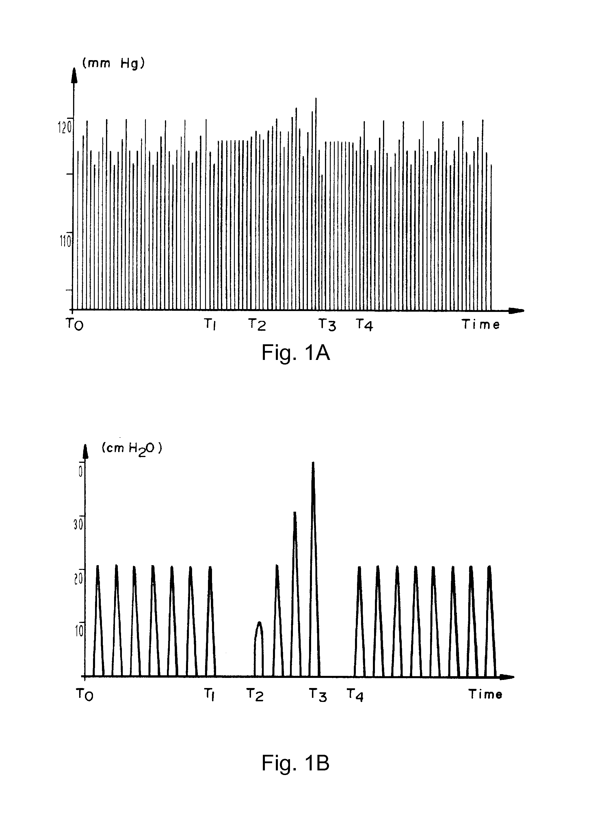
[0030]Referring to the drawings in particular, FIG. 1A and FIG. 1B illustrate hemodynamic and respiratory data which may occur during the use of the method disclosed in U.S. Pat. No. 5,769,082. FIG. 1B illustrates an example of the airway pressure applied by a mechanical ventilator in cm H20, as a function of time. T1 to T2 indicates the apnea period. From T2 to T3, the airway pressure of successive tides is increased. FIG. 1A illustrates an example of blood pressure values in mm Hg as a function of time, measured during the mechanical ventilation pattern of FIG. 1B. It can be seen in the interval from T2 to T3, that blood pressure variance increases as a result of the increasing airway pressure. In this interval, the higher blood pressure increases whereas the lower blood pressure decreases. The slope of a line connecting the lower blood pressures may be determined in the RSVT.

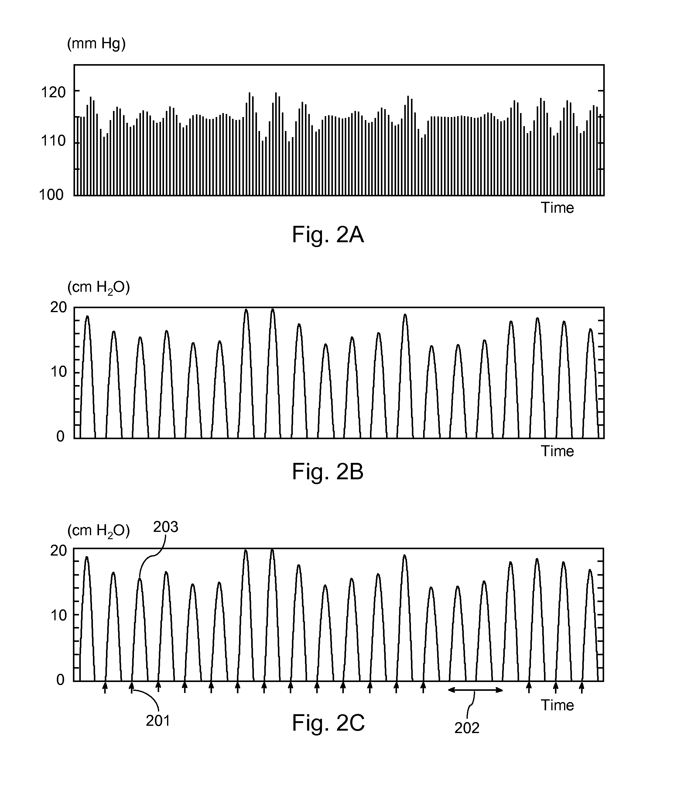
[0031]FIG. 2A and FIG. 2B illustrate an example of hemodynamic and respiratory data which may occur when s...


PUM


Abstract

A system for providing an indication of cardiovascular function, includes a respiration input (1) for receiving a respiration-related signal indicative of a physical property of respiration gases administered to a patient. A hemodynamic input (2) is provided for receiving a hemodynamic-related signal indicative of a hemodynamic property. An inspiration detector (3) is provided for processing the respiration-related signal to detect times of inspiration and a measure of the size of the inspiration. A correlator (5) is provided for correlating the sizes of inspiration with the hemodynamic-related signal, to obtain the indication of cardiovascular function. The respiration-related signal is indicative of inspiration pressure, inspiration volume, or inspiration flow. The hemodynamic-related signal is indicative of blood pressure.

Description

CROSS REFERENCE TO RELATED APPLICATIONS[0001]This application claims the benefit of priority under 35 U.S.C. ยง119 of European Patent Application EP 10 158 025.6 filed Mar. 26, 2010, the entire contents of which are incorporated herein by reference.FIELD OF THE INVENTION[0002]The invention relates to a system for providing an indication of cardiovascular function. The invention further relates to a method of providing an indication of cardiovascular function. The invention further relates to a computer program product for providing an indication of cardiovascular function.BACKGROUND OF THE INVENTION[0003]In the critical care department of a hospital, there are patients that are seriously ill and of whom the cardiovascular function needs continuous attention. Often these patients also are mechanically ventilated, either continuously or during surgery. The monitoring of the cardiovascular status of these patients is done by continuous measurement of the blood pressure and the heart rat...

Claims


Application Information

Patent Timeline
29 Sep 2011
Publication
US20110237959A1
IPC
A61B5/0205
CPC
A61M16/00; A61B5/021; A61M16/0084; A61B5/087; A61B5/091; A61B5/0816; A61M16/0051; A61M16/021
Inventors
VAN HOUWELINGEN, MARC