
Down-the-hole drill hammer having an extendable drill bit assembly

a drill bit and extension technology, which is applied in the direction of drilling machines, drilling methods, borehole drives, etc., can solve the problems of undersized holes through which the casing cannot fit, the drilling is not cost-effective and reliable, and the drilling is not easy to be carried out. , to achieve the effect of simple and reliable drilling bit, simple and reliable cutting face, and cost-effective and reliable under reaming operations

Active Publication Date: 2011-10-06
CENTER ROCK INC
View PDF6 Cites 13 Cited by
  • Summary
  • Abstract
  • Description
  • Claims
  • Application Information

AI Technical Summary

Benefits of technology

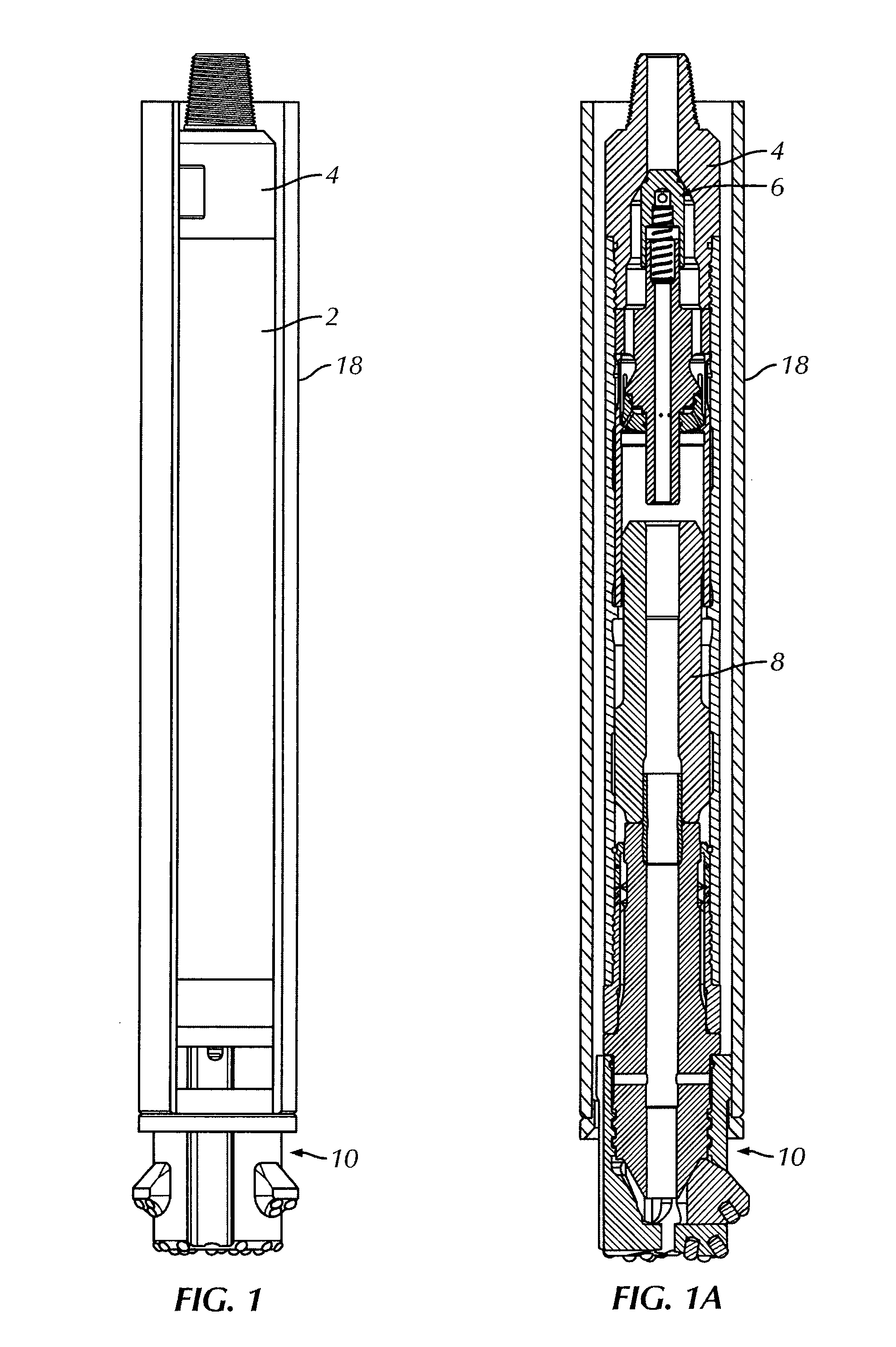
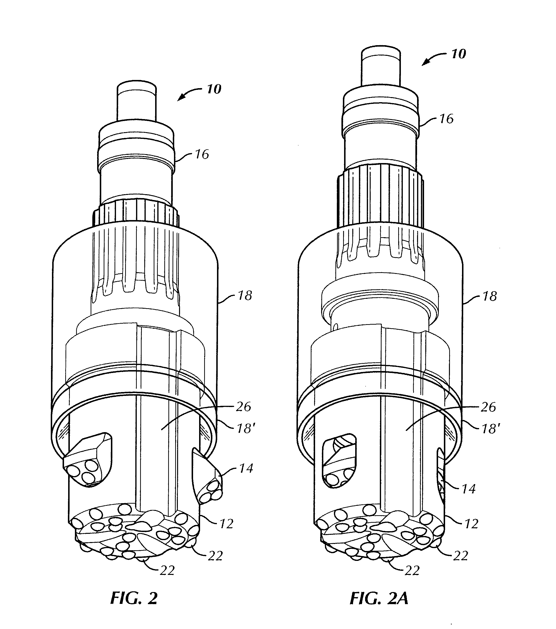
[0006]In accordance with the present invention, the problem of cost-effective and reliable under reaming operations is solved by engendering a drill bit assembly for a percussive down-the-hole drill hammer having extendable drill bits to enlarge its cutting face diameter. The extendable drill bits are extended upon full engagement of a drill stem with a pilot drill bit. In this way, a simple and reliable drill bit is provided that can effectively and efficiently perform under reaming operations.

Problems solved by technology

While such systems are effective, they are costly to use for micropiling since the kerf-cutting ring bit is left (i.e., discarded) in the hole and because of the high number of piles associated with micropiling.
Such systems have the operating cost advantage of not leaving a ring bit in the hole, but they do have operational limitations.
If borehole contact is lost, it is likely that the wing will not stay in position, thus leaving an undersized hole through which the casing will not fit.
A known limitations of such lugs is that they require constant contact with the bore hole bottom to remain in the extended configuration.
Therefore, if the ground surface cannot supply ample back pressure to extend the lugs (such as when advancing through sand, voids or other similar conditions) the system will drill an undersized hole that will not allow the casing to clear the hole.

Method used


Image

  • Down-the-hole drill hammer having an extendable drill bit assembly
  • Down-the-hole drill hammer having an extendable drill bit assembly
  • Down-the-hole drill hammer having an extendable drill bit assembly

Examples


Embodiment Construction

[0034]Reference will now be made in detail to the present embodiment of the invention illustrated in the accompanying drawings. Wherever possible, the same or like reference numbers will be used throughout the drawings to refer to the same or like features. It should be noted that the drawings are in simplified form and are not drawn to precise scale. In reference to the disclosure herein, for purposes of convenience and clarity only, directional terms such as top, bottom, above, below and diagonal, are used with respect to the accompanying drawings. The words “proximal” and “distal” refer to directions toward and away from, respectively, the geometric center of the identified element and designated parts thereof. The term “distal” also means towards the drill bit end of the DHD hammer, while the term “proximal” also means towards the backhead end of the DHD hammer. Such directional terms used in conjunction with the following description of the drawings should not be construed to l...


PUM


Abstract

A down-the-hole drill hammer assembly includes a casing, a drill stem, a drilling lug segment and a pilot drill bit is provided. The drill stem is housed within the casing and includes an abutment surface. The drilling lug segment is slidably engaged with a distal end of the drill stem and movable between an initial configuration and an extended configuration. The drilling lug segment includes a proximal end engageable with the abutment surface of the drilling lug segment. The drill stem is movable between first and second positions within the pilot drill bit. In moving to the second position, the drill stem slidingly engages the drilling lug segment and moves the drilling lug segment to the extended configuration.

Description

CROSS-REFERENCE TO RELATED APPLICATIONS[0001]This application is entitled to and claims the benefit of the priority pursuant to 35 U.S.C. §119(e) of U.S. Provisional Patent Application No. 61 / 319,957, filed Apr. 1, 2010, the entire disclosure of which is hereby incorporated herein by reference.BACKGROUND OF THE INVENTION[0002]The present invention relates to a type of down-the-hole percussive drilling hammer having a drilling bit with the ability to drill a hole with one outer diameter and then reduce its overall outer diameter for extraction from the hole through a pipe or casing that is inserted while the hole is being drilled. Insertion of a pipe into the ground is a common practice for many types of construction projects. For example, water wells use a casing for sealing contaminated surface water from potable deeper water. Sometimes the casing is only installed by under-reaming to prevent the hole from caving or collapsing into itself. Foundations commonly use a process called ...

Claims


Application Information

Patent Timeline
IPC IPC(8): E21B10/34E21B4/00
CPCE21B4/06E21B10/32E21B7/208
Inventor LYON, LELAND H.LAY, WARREN THOMAS
Owner CENTER ROCK INC
Learn More