
Robotic system and method of use

Active Publication Date: 2011-10-06
ROBOTEX
View PDF2 Cites 81 Cited by
  • Summary
  • Abstract
  • Description
  • Claims
  • Application Information

AI Technical Summary

Benefits of technology

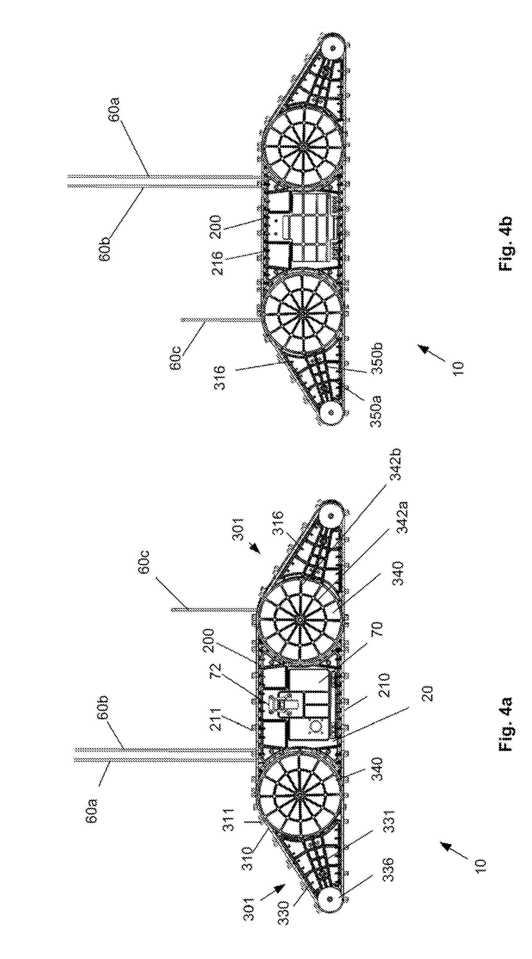
[0024]The system can have a track guide or retention structure on the body. The track guide structure can be mated to the outside edge of the second inner nub on the second lateral side. The track guide or retention structure can include vanes on the inside of the pulley. For example, a second wheel cap can be on the chassis-side of the flipper or mobility device pulley, for example, to help keep the track guided.
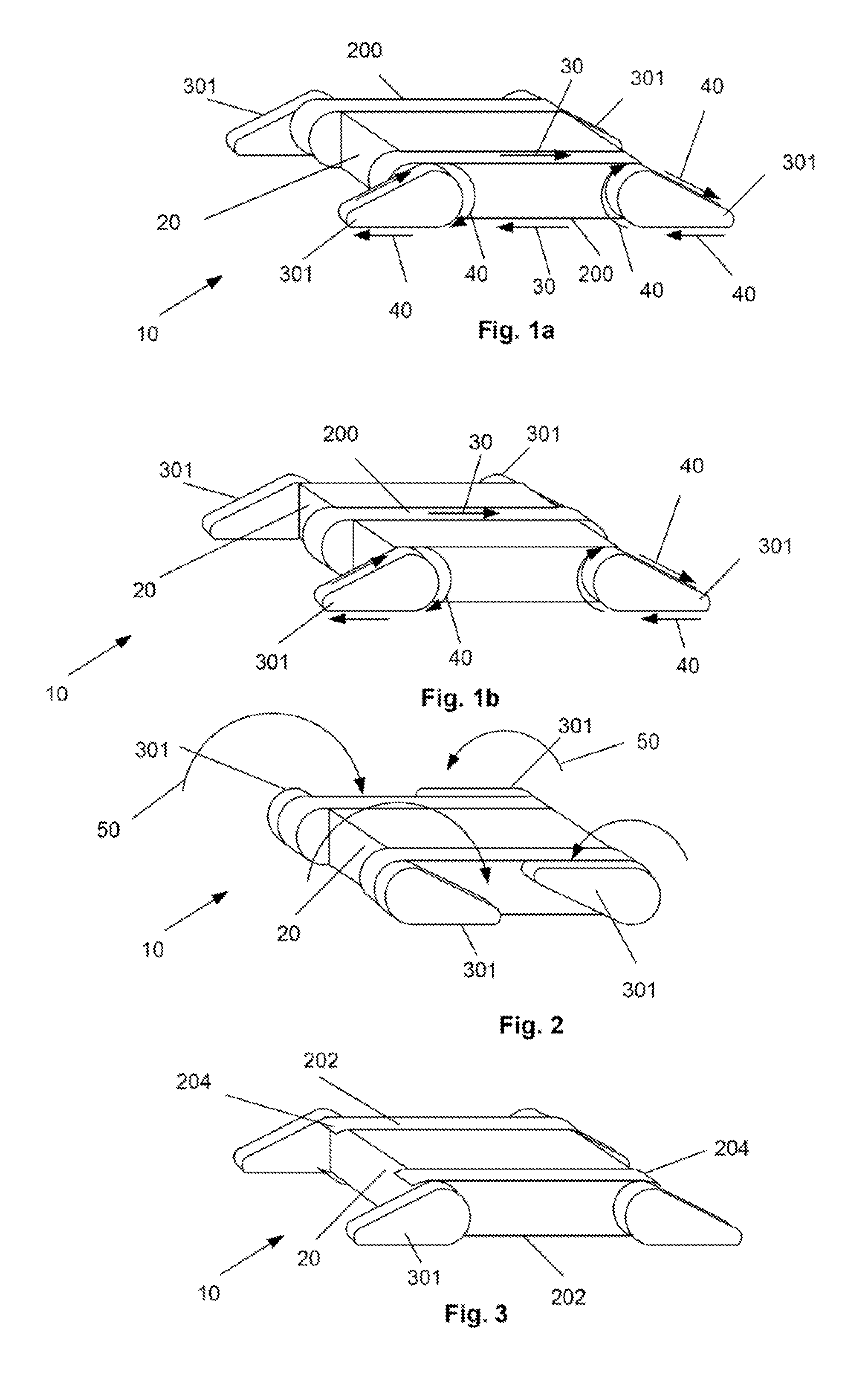
[0048]A robotic vehicle system having a body and a pair of main tracks or mobility devices is disclosed. The main tracks can be angled (i.e., non-parallel) with respect to each other. The robotic vehicle system can have a drive system for driving the pair of main tracks. The main tracks can be toe-in or toe-out with respect to each other. The toe-in or tow-out angle can be from greater than about 0 degrees to about 90 degrees, for example about 10 degrees. The robotic system can have a first mobility assistance device attached to the body, and a second mobility assistance device attached to the body. The angle of the main tracks with respect to each other can be adjusted during use. The tracks can be toe-in for enhanced straight line stability and / or toe-out for enhanced turning sensitivity.

Problems solved by technology

Such vehicles are often insufficiently robust for purposes other than racing or entertainment, and rarely have tooling or payloads to accomplish task other than mobility.

Method used


Image

  • Robotic system and method of use
  • Robotic system and method of use
  • Robotic system and method of use

Examples


Embodiment Construction

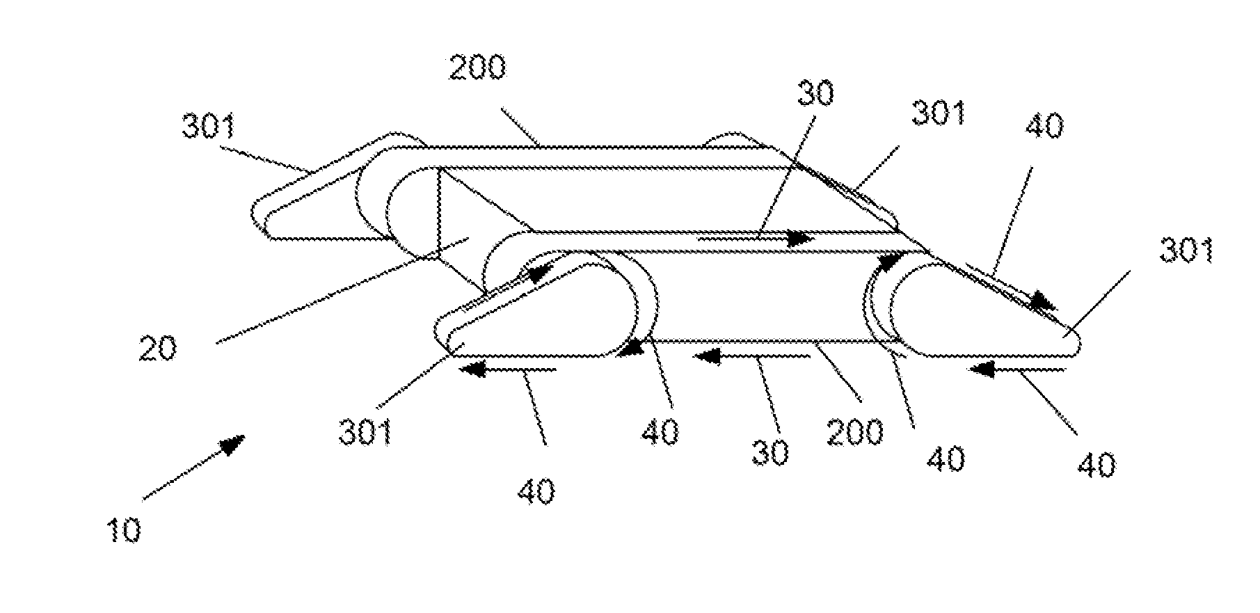
[0076]FIGS. 1a and 1b illustrate a robotic system 10 that can be used for remotely transporting a payload and the robotic system itself. The robotic system is configured to traverse a multitude of terrain types including stairs, rubble, water barriers, and to push open and pass through doors. The robotic system can be in an expanded configuration to extend the effective wheelbase and / or track base (i.e., the length from the distal end of the longitudinally outermost wheel or track on a first longitudinal end of the system to distal end of the longitudinally outermost opposite wheel or track on a second longitudinal end of the system).

[0077]The robotic system 10 can have a chassis frame 101. The chassis frame 101 can have plates mounted to the chassis frame 101. The chassis frame 101 and plates can form a dust-proof, and / or water-proof body 20 or chassis 100. For example, the plates can form the entire outside surface, be sealed with gaskets and / or caulking and / or sealant, and have n...


PUM


Abstract

A robotic system that can have a body and four flippers is described. Any or all of the flippers can be rotated. The flippers can have self-cleaning tracks. The tracks can be driven or passive. The robotic system can be controlled by, and send audio and / or video to and / or from, a remote operator control module. The methods of using and making the robotic system are also described.

Description

BACKGROUND[0001]1. Technical Field[0002]This invention relates generally to the robotics field, and more specifically to a new and useful robotic system in the robotics field.[0003]2. Summary of the Art[0004]Ground-based remote-controlled robotic systems exist for a number of purposes. Unmanned Ground Vehicles (UGV), such as Soldier UGVs (SUGVs) are small, remotely controlled robotic systems, often purposed for military use. The UGVs can provide remote surveillance images and sensed information. UGVs can be tele-operated in an area local to a controlling dismounted soldier, and be transported to the operational area with dismounted soldiers as stowage. The UGVs operate in rural and urban terrain, and often are needed to climb stairs, pass through doorways, operation in subterranean structures, and traverse rubble or other obstacles.[0005]Domestic police, including Special Weapons and Tactics (SWAT) Teams, use UGVs for domestic policing, including performing “hard clears” or other hi...

Claims


Application Information

Patent Timeline
IPC IPC(8): B62D55/088B62D55/00B62D55/12
CPCB62D55/075B62D55/0885B62D55/12Y10S901/01B25J5/00A63H17/14B62D55/06B62D55/08
Inventor GETTINGS, NATHAN D.GETTINGS, ADAM M.PENN, TAYLOR J.SILER, III, EDWARD J.STEVENS, ANDREW G.
Owner ROBOTEX
Learn More