Extracorporeal blood treatment machine

a blood treatment machine and user interface technology, applied in the field of user interface for a machine for extracorporeal blood treatment, can solve the problems of complicated and laborious preparation procedures, and achieve the effects of rapid execution, rapid learning, and convenient us

Active Publication Date: 2011-10-06
GAMBRO LUNDIA AB
View PDF5 Cites 41 Cited by
  • Summary
  • Abstract
  • Description
  • Claims
  • Application Information

AI Technical Summary

Benefits of technology

[0015]An advantage of the invention is that it makes rapid learning possible, as well as rapid execution even by a non-expert user, of the procedural steps necessary for preparation of the machine for extracorporeal blood treatment.
[0016]A further advantage of the present invention is to provide a user interface which is easy to use, and by means of which times for carrying out the preliminary stages of machine preparation for extracorporeal blood treatment can be reduced—for example, in relation to the mounting of the single-use parts of the apparatus on the machine.
[0017]The aims and advantages and more besides are all achieved by the present invention, as it is characterised in one or more of the appended claims.
[0018]In a characteristic of the invention, the selection of any touch key located in a first area of a display will determine display, in a second area of the screen, of a corresponding image, each touch key being associated to a respective image.
[0019]In an embodiment of the invention, the images associated to the touch keys are shown in a different way, i.e. not at the same time in a second area of the display.
[0020]In an embodiment of the invention, the images displayed on the second area of the screen are, at least partially, different one from another.

Problems solved by technology

These preparation procedures can be very long, complicated and laborious, especially with intensive therapy dialysis machines, where the machine operator is often not specialised in the use of these apparatus, and where the time factor is critical as the patient is often in quite a serious condition and needs as fast an intervention as possible.

Method used


Image

  • Extracorporeal blood treatment machine
  • Extracorporeal blood treatment machine
  • Extracorporeal blood treatment machine

Examples


Embodiment Construction

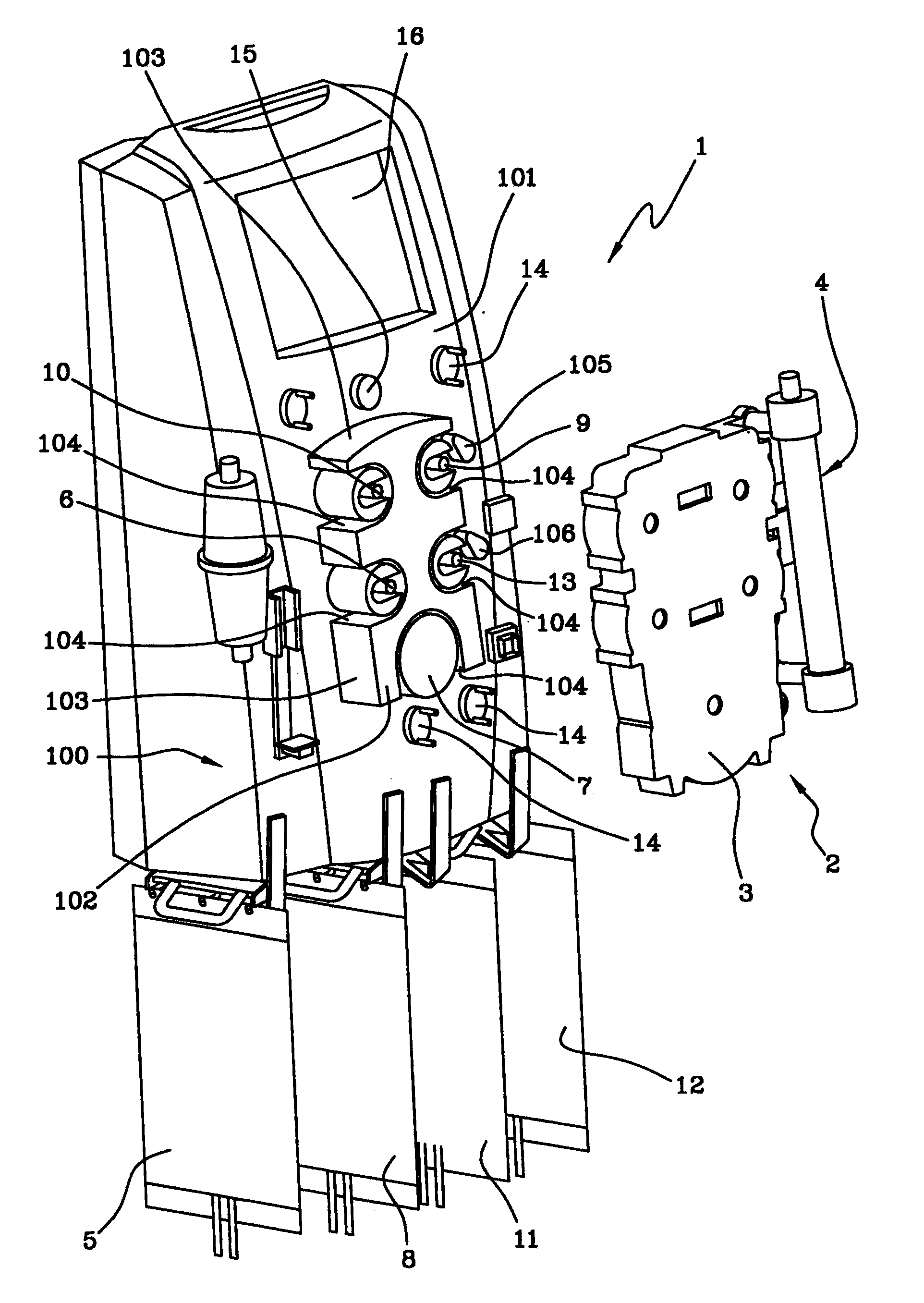
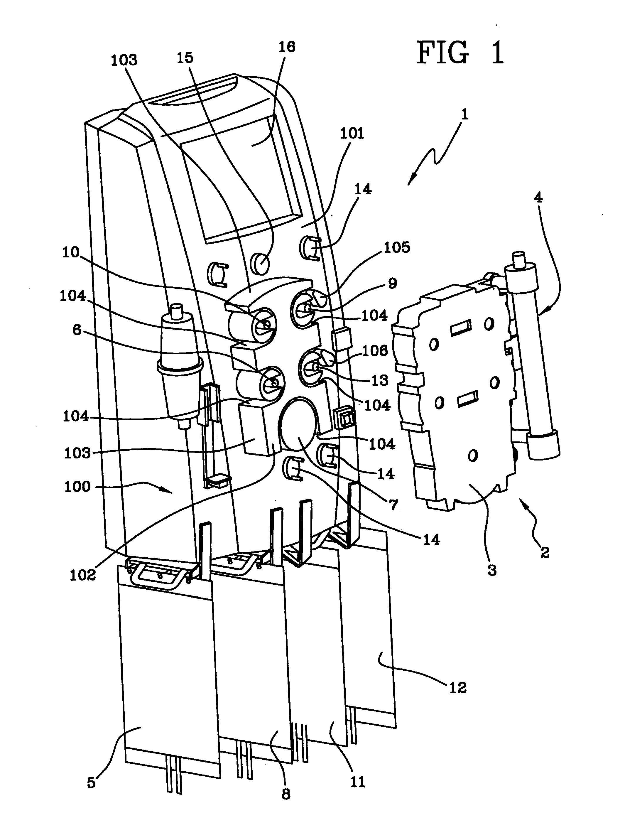
[0035]With reference to FIG. 1, 1 denotes in its entirety a machine for extracorporeal blood treatment, represented in the illustrated embodiment by a dialysis machine which is suitable for intensive treatment of acute kidney failure. 2 denotes in its entirety an integrated module which can be coupled to the dialysis machine 1. The integrated module 2 is constituted by a combination of at least one support element 3 of a distribution circuit (of known type and not illustrated) arranged on the support element 3, and a blood treatment unit 4. The blood treatment unit 4 can be, for example, a plasma filter, a hemodialysis filter, a hemofiltration filter, or a different unit.

[0036]The hydraulic circuit, which is completed by a combination of the integrated module 2 and the machine 1, comprises a blood circuit which removes blood from a patient, for example via a catheter inserted in a vascular access of the patient, and takes the blood though a blood removal line to the treatment unit 4...


PUM

PropertyMeasurementUnit
areaaaaaaaaaaa
timeaaaaaaaaaa
flow rateaaaaaaaaaa

Abstract

A user interface for a machine for extracorporeal blood treatment comprises a touch screen and a controller programmed to display on a screen (16) a display in which two distinct areas are arranged, one of which (161) exhibits a series of touch keys (17). Activation of any one touch key (17) causes visualization of an image in a second area (162) of the screen. The images are displayed alternatively and are at least partly different one from another. Each touch key (17) is associated to an instruction, or to a group of instructions, all concerned with readying the machine for use. Each image is a pictograph of a configuration of the machine, correlated with an instruction associated to the touch key (17) selected. The operator is aided in making the machine ready for treatment.

Description

BACKGROUND OF THE INVENTION[0001]The invention relates to a user interface for a machine for extracorporeal blood treatment, as well as to a machine for extracorporeal blood treatment comprising the user interface.[0002]Specifically, though not exclusively, the invention is usefully applied in the field of dialysis machines, such as for example machines for intensive treatment for acute renal failure.[0003]In particular the invention relates to a user interface according to the preamble of the first claim.[0004]Document WO 98 / 35747 teaches a dialysis machine, suitable for carrying out periodical dialysis treatments—including domestic treatment—which is provided with a user interface such as the one described in the preamble of the first claim, in which the user interface has a programmed controller that displays various layouts on a touch-screen monitor, in at least one of which layouts (FIG. 5) the screen is sub-divided into various areas. A first of these areas exhibits touch keys...

Claims


Application Information

Patent Timeline
Patent Type & Authority Applications(United States)
IPC IPC(8): B01D21/30A61M1/14A61M1/16A61M1/36A61M37/00
CPCA61M1/367A61M2205/505A61M2205/12A61M1/14A61M1/16A61M1/36G16H40/63A61M1/362264A61M1/36225A61M60/585A61M1/1601G16H20/17A61M1/3626A61M1/3672G06F3/04847G06F3/04886
Inventor FERRARINI, LORENZAPELLETIER, DANIELLEZACCARELLI, MASSIMOLETTERI, JEFFREY J.
Owner GAMBRO LUNDIA AB
Why Eureka
Try Eureka